《通信原理实验》课程电子教案(PPT讲稿)MATLAB与通信仿真(英文)Chapter 2 Transmitters and Receivers
Transmitters and Receivers Generalized Transmitter Generalized Receiver The Superheterodyne Receiver Minimum Sampling frequency
Transmitters and Receivers Generalized Transmitter Generalized Receiver The Superheterodyne Receiver Minimum Sampling frequency
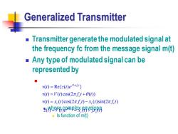
Generalized Transmitter Transmitter generate the modulated signal at the frequency fc from the message signal m(t) Any type of modulated signal can be represented by ■ v(t)=Refz(t)e v(t)=V(t)cos(2πft+θt) v(t)=x.(t)cos(2πft)-x,(t)sin(2πft) (h9呢9mp災YPR8 Is function of m(t)
Generalized Transmitter ◼ Transmitter generate the modulated signal at the frequency fc from the message signal m(t) ◼ Any type of modulated signal can be represented by ◼ ◼ where complex envelope ◼ Is function of m(t) 2 ( ) Re{ ( ) } ( ) ( )cos(2 ( )) ( ) ( )cos(2 ) ( )sin(2 ) c j f t c c c s c v t z t e v t V t f t t v t x t f t x t f t = = + = − ( ) ( ) ( ) ( ) ( ) j t c s z t V t e x t jx t = = +
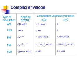
Complex envelope Type of Mapping Corresponding Quadrature modulation modulation z(m(t)) (t) x(t) AM A.[1+m(t] A.1+m(t)] 0 DSB A.m(t) A.m(t) 0 PM Lekmr) A cos(km(t)) 4 sin(km(t)) FM e m A.cos(k,['m(r)dr)Asin(k,fm()dr) SSB A.[m(t)±jm(t)] Am(t)) ±jAm(t)
Complex envelope ( ) ( ) [1 ( )] ( ) [ ( ) ( )] p t f c c jk m t c jk m d c c A m t A m t A e A e A m t jm t − + [1 ( )] ( ) cos( ( )) cos( ( ) ) ( ) c c c p t c f c A m t A m t A k m t A k m d A m t − + 0 0 sin( ( )) sin( ( ) ) ( ) c p t c f c A k m t A k m d jA m t − Type of modulation AM DSB PM FM SSB Mapping z(m(t)) Corresponding Quadrature modulation xc (t) xs (t)
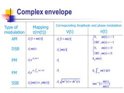
Complex envelope Type of Mapping Corresponding Amplitude and phase modulation modulation z(m(t)) V(t) 0(t) AM A,1+m(t)] A.1+m) 0, m(t)>-1 180°,m(t)0 180°,m(t)<0 PM A.e。mo) A k,m(t) FM A kimr)dr SSB A.[m(t)±jm(t)] AVm2()+m2(0 an'±m m(t)
Complex envelope 2 2 1 ( ) ( ) ( ) ( ) c c c c c A m t A m t A A A m t m t + + 1 0, ( ) 1 180 , ( ) 1 0, ( ) 0 180 , ( ) 0 ( ) ( ) ( ) tan [ ] ( ) p t f m t m t m t m t k m t k m d m t m t − − − − Type of modulation AM DSB PM FM SSB Mapping z(m(t)) Corresponding Amplitude and phase modulation V(t) (t) ( ) ( ) [1 ( )] ( ) [ ( ) ( )] p t f c c jk m t c jk m d c c A m t A m t A e A e A m t jm t − +
Generalized Transmitter ■Two canonical form AM-PM generation technique Quadrature generation technique Choice is up to designer Maximize performance Minimize cost Based upon the available device and circuits
Generalized Transmitter ◼ Two canonical form ◼ AM-PM generation technique ◼ Quadrature generation technique ◼ Choice is up to designer ◼ Maximize performance ◼ Minimize cost ◼ Based upon the available device and circuits
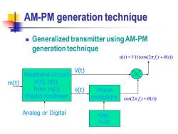
AM-PM generation technique Generalized transmitter using AM-PM generation technique u(t)=V(t)cos(2πft+θt) V() Baseband circuits m(t) V(t),0( from m(t) 0(t) Phase Maybe nonlinear modulator cos(2πft+0(t) Analog or Digital Osc. f=fc
AM-PM generation technique ◼ Generalized transmitter using AM-PM generation technique Baseband circuits V(t), (t) from m(t) Maybe nonlinear Osc. f=fc Phase modulator m(t) V(t) (t) cos(2 ( )) c f t t + ( ) ( )cos(2 ( )) u t V t f t t = + c Analog or Digital
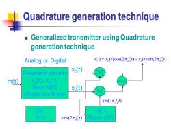
Quadrature generation technique Generalized transmitter using Quadrature generation technique Analog or Digital u(t)=x.(t)cos(2πft)-x,(t)sin(2πft) Baseband circuits (t) m(t) x(t),x (t) from m(t) x(t) Maybe nonlinear sin(2πft) Osc. -90° f=fc cos(2πfCt) Phase shift
Quadrature generation technique ◼ Generalized transmitter using Quadrature generation technique Baseband circuits xc (t), xs (t) from m(t) Maybe nonlinear Osc. f=fc -90 Phase shift m(t) xc (t) xs (t) cos(2 ) c f t ( ) ( )cos(2 ) ( )sin(2 ) u t x t f t x t f t = − c c s c Analog or Digital sin(2 ) c f t
Generalized Receiver Extracting the source information from received modulated signal ■Corrupted by noise Often it is a replica of the message signal Two main classes of receiver TRF(Tuned Radio Frequency) -Not popular because hard to design and implement Superhetrodyne Most receiver uses this technique
Generalized Receiver ◼ Extracting the source information from received modulated signal ◼ Corrupted by noise ◼ Often it is a replica of the message signal ◼ Two main classes of receiver ◼ TRF(Tuned Radio Frequency) ◼ Not popular because hard to design and implement ◼ Superhetrodyne ◼ Most receiver uses this technique
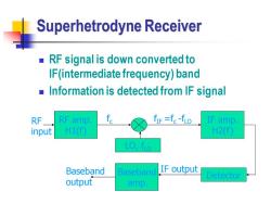
Superhetrodyne Receiver RF signal is down converted to IF(intermediate frequency)band Information is detected from IF signal RF RF amp. f fIF =fc-fLo IF amp. input H1(f) H2() LO,fio Baseband Baseband IF output Detector output amp
Superhetrodyne Receiver ◼ RF signal is down converted to IF(intermediate frequency) band ◼ Information is detected from IF signal RF amp. H1(f) LO, fLO IF amp. H2(f) Detector Baseband amp. RF input Baseband IF output output fc fIF =fc -fLO
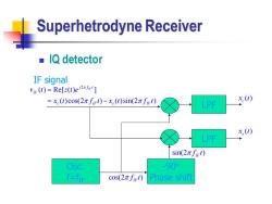
Superhetrodyne Receiver ■IQ detector IF signal v(t)=Re[=(t)e2] =xe(t)cos(2πfirt)-x,(t)sin(2πfirt) x.(t) LPF x,() LPF sin(2πfrt) Osc. -90° f-fie cos(2πfiFl) Phase shift
Superhetrodyne Receiver ◼ IQ detector Osc. f=fIF -90 cos(2 ) f t IF Phase shift sin(2 ) IF f t IF signal 2 ( ) Re[ ( ) ] ( ) cos(2 ) ( ) sin(2 ) IF j f t IF c IF s IF v t z t e x t f t x t f t = = − LPF LPF ( ) c x t( ) s x t
按次数下载不扣除下载券;
注册用户24小时内重复下载只扣除一次;
顺序:VIP每日次数-->可用次数-->下载券;
- 《通信原理实验》课程电子教案(PPT讲稿)MATLAB与通信仿真(英文)Chapter 2 Analog Modulation(Frequency Modulation、Phase Modulation).ppt
- 《通信原理实验》课程电子教案(讲稿)MATLAB与通信仿真(英文)Chapter 7 Spread Spectrum Communication Systems.doc
- 《通信原理实验》课程电子教案(PPT讲稿)MATLAB与通信仿真(英文)Chapter 2 Analog Modulation(SSB – AM).ppt
- 《通信原理实验》课程电子教案(PPT讲稿)MATLAB与通信仿真(英文)Chapter 2 Analog Modulation(Conventional AM).ppt
- 《通信原理实验》课程电子教案(PPT讲稿)MATLAB与通信仿真(英文)Chapter 2 Analog Modulation(AM,Amplitude Modulation).ppt
- 《通信原理实验》课程电子教案(讲稿)MATLAB与通信仿真(英文)Chapter 1 Basic Matlab.doc
- 《通信原理实验》课程电子教案(PPT讲稿)MATLAB与通信仿真电子教案_第1章 matlab基础知识.ppt
- 《通信原理实验》课程电子教案(PPT讲稿)MATLAB与通信仿真电子教案_第3章 图形处理与simulink仿真.ppt
- 《通信原理实验》课程电子教案(PPT讲稿)MATLAB与通信仿真电子教案_第2章 matlab语言入门.ppt
- 《通信原理实验》课程电子教案(PPT讲稿)MATLAB与通信仿真电子教案_matlab在通信中的应用(模拟调制系统).ppt
- 《通信原理实验》课程电子教案(PPT讲稿)MATLAB与通信仿真电子教案_matlab在通信中的应用(模拟信号的数字传输).ppt
- 《通信原理实验》课程电子教案(PPT讲稿)MATLAB与通信仿真电子教案_matlab在通信中的应用(二进制基带系统).ppt
- 《通信原理实验》课程电子教案(PPT讲稿)MATLAB与通信仿真电子教案_matlab在通信中的应用(PSK频带传输系统).doc
- 《通信原理实验》课程电子教案(PPT讲稿)FPGA通信系统设计——第四讲 DDS信号发生器周期信号的傅里叶级数拟合.ppt
- 《通信原理实验》课程电子教案(讲稿)FPGA通信系统设计——第四讲 方波信号展开为傅里叶级数.doc
- 《通信原理实验》课程电子教案(讲稿)FPGA通信系统设计——第四讲 实验四 DDS信号发生器与周期函数的傅里叶级数拟合.doc
- 《通信原理实验》课程电子教案(讲稿)FPGA通信系统设计——第四讲 DDS信号发生器周期信号的傅里叶级数拟合.doc
- 《通信原理实验》课程电子教案(PPT讲稿)FPGA通信系统设计——第二讲 System Generator for DSP.ppt
- 《通信原理实验》课程电子教案(讲稿)FPGA通信系统设计——第二讲 实验二 Nexys 3实验板及设计软件.doc
- 《通信原理实验》课程电子教案(讲稿)FPGA通信系统设计——第三讲 实验三 DA芯片的型号及时序.pdf
- 《通信原理实验》课程电子教案(PPT讲稿)MATLAB与通信仿真(英文)Chapter 3 Analog-to-Digital Conversion(Preview、Measure of Information、Quantization).ppt
- 《通信原理实验》课程电子教案(PPT讲稿)MATLAB与通信仿真(英文)Chapter 3 Analog-to-Digital Conversion(Pulse Amplitude Modulation、Pulse Code Modulation).ppt
- 《通信原理实验》课程电子教案(PPT讲稿)MATLAB与通信仿真(英文)Chapter 4 Baseband Digital Transmission(Binary Signal Transmission).ppt
- 《通信原理实验》课程电子教案(PPT讲稿)MATLAB与通信仿真(英文)Chapter 4 Baseband Digital Transmission(Multiamplitude Signal Transmission).ppt
- 《通信原理实验》课程电子教案(PPT讲稿)MATLAB与通信仿真(英文)Chapter 4 Baseband Digital Transmission(Multidimensional Signals).ppt
- 《通信原理实验》课程电子教案(PPT讲稿)MATLAB与通信仿真(英文)Chapter 5Digital Transmission Through Bandlimited Channels.ppt
- 《通信原理实验》课程电子教案(PPT讲稿)MATLAB与通信仿真(英文)Chapter 6 Binary Modulated Bandpass Signaling(1/3).ppt
- 《通信原理实验》课程电子教案(PPT讲稿)MATLAB与通信仿真(英文)Chapter 6 Binary Modulated Bandpass Signaling(2/3).ppt
- 《通信原理实验》课程电子教案(PPT讲稿)MATLAB与通信仿真(英文)Chapter 6 Binary Modulated Bandpass Signaling(3/3).ppt
- 《通信原理实验》课程电子教案(PPT讲稿)Verilog HDL数字系统设计与综合实验——第01讲 HDL语言概述.ppt
- 《通信原理实验》课程电子教案(PPT讲稿)Verilog HDL数字系统设计与综合实验——第02讲 Verilog HDL语言基础.ppt
- 《通信原理实验》课程电子教案(PPT讲稿)Verilog HDL数字系统设计与综合实验——第03讲 门级与结构建模.ppt
- 《通信原理实验》课程电子教案(PPT讲稿)Verilog HDL数字系统设计与综合实验——第04讲 数据流建模.ppt
- 《通信原理实验》课程电子教案(PPT讲稿)Verilog HDL数字系统设计与综合实验——第05讲 行为建模(1/2).ppt
- 《通信原理实验》课程电子教案(PPT讲稿)Verilog HDL数字系统设计与综合实验——第06讲 行为建模(2/2).ppt
- 《通信原理实验》课程电子教案(PPT讲稿)Verilog HDL数字系统设计与综合实验——第07讲 综合建模与仿真.ppt
- 《通信原理实验》课程电子教案(PPT讲稿)Verilog HDL数字系统设计与综合实验——第08讲 可综合设计.ppt
- 《通信原理实验》课程电子教案(PPT讲稿)嵌入式系统设计实验——第1章 嵌入式系统概述.ppt
- 《通信原理实验》课程电子教案(PPT讲稿)嵌入式系统设计实验——第2章 嵌入式系统工程设计.ppt
- 《通信原理实验》课程电子教案(PPT讲稿)嵌入式系统设计实验——第3章 ARM7体系结构(1/2).ppt
