《通信原理实验》课程电子教案(PPT讲稿)MATLAB与通信仿真(英文)Chapter 4 Baseband Digital Transmission(Multiamplitude Signal Transmission)

Baseband Digital Transmission Multiamplitude Signal Transmission
Baseband Digital Transmission Multiamplitude Signal Transmission

Binary Vs.Multiamplitude signal Binary signal 1 bit of information Two level to represent 0 and 1 If we use multiple amplitude levels We can transmit multiple bits per signal waveform ■Question Probability of Error Vs.Bandwidth ??
Binary Vs. Multiamplitude signal ◼ Binary signal ◼ 1 bit of information ◼ Two level to represent 0 and 1 ◼ If we use multiple amplitude levels ◼ We can transmit multiple bits per signal waveform ◼ Question ◼ Probability of Error Vs. Bandwidth ???

Signal waveform with 4 amplitude levels Normalized pulse whose energy is 1 80=序0ss7 0 ,otherwise Consider 4 equally spaced Amplitude ■Am=(2m-3)d,m=0,1,2,3 ■0rAn={-3d,-d,d,3d0 4 waveform called PAM(Pulse Amplitude Modulated) signal ■Snm(t)=Ang(t),0≤t≤T See figure 4.19,page 190
Signal waveform with 4 amplitude levels ◼ Normalized pulse whose energy is 1 ◼ ◼ Consider 4 equally spaced Amplitude ◼ ◼ Or ◼ 4 waveform called PAM(Pulse Amplitude Modulated) signal ◼ ◼ See figure 4.19, page 190 1 , 0 ( ) 0 , t T g t T otherwise = A m d m m = − = (2 3) , 0,1, 2,3 { 3 , , ,3 } A d d d d m = − − s t A g t t T m m ( ) ( ), 0 =

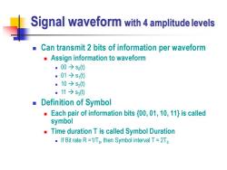
Signal waveform with 4 amplitude levels Can transmit 2 bits of information per waveform Assign information to waveform ■00→s0) ■01→s ·10→s2() .11→S3() ■ Definition of Symbol Each pair of information bits (00,01,10,11}is called symbol Time duration T is called Symbol Duration If Bit rate R=1/Tp,then Symbol interval T=2Tp
Signal waveform with 4 amplitude levels ◼ Can transmit 2 bits of information per waveform ◼ Assign information to waveform ◼ 00 → s0 (t) ◼ 01 → s1 (t) ◼ 10 → s2 (t) ◼ 11 → s3 (t) ◼ Definition of Symbol ◼ Each pair of information bits {00, 01, 10, 11} is called symbol ◼ Time duration T is called Symbol Duration ◼ If Bit rate R =1/Tb , then Symbol interval T = 2Tb

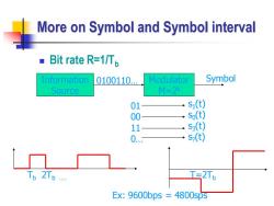
More on Symbol and Symbol interval Bit rate R=1/Tp Information 0100110 Modulator Symbol Source M=2水 01 S1(t) 00 so(t) 1 S() 0 s(t) Tp 2Tb. T=2Tb Ex:9600bps 4800sps
More on Symbol and Symbol interval ◼ Bit rate R=1/Tb Information Source 0100110. Modulator M=2k Symbol 01 00 11 0. s1 (t) s0 (t) s3 (t) s? (t) Tb 2Tb . T=2Tb Ex: 9600bps = 4800sps

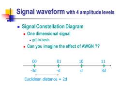
Signal waveform with 4 amplitude levels Signal Constellation Diagram One dimensional signal ■g()is basis Can you imagine the effect of AWGN ? 00 01 10 11 -3d -d d 3d Euclidean distance =2d
Signal waveform with 4 amplitude levels ◼ Signal Constellation Diagram ◼ One dimensional signal ◼ g(t) is basis ◼ Can you imagine the effect of AWGN ?? -3d -d d 3d 00 01 10 11 Euclidean distance = 2d

Received Signal ■ AWGN channel assumption ■r(t)=S,(t)+n(t),m=0,1,2,3,0≤t≤T White Gaussian process With power spectrum No/2 Receiver determines which of 4 signal waveform was transmitted by observing the received signal r(t) Optimum receiver minimizes the probability of error
Received Signal ◼ AWGN channel assumption ◼ ◼ Receiver determines which of 4 signal waveform was transmitted by observing the received signal r(t) ◼ Optimum receiver minimizes the probability of error ( ) ( ) ( ), 0,1, 2,3, 0 i r t s t n t m t T = + = White Gaussian process With power spectrum N0 /2

Optimum receiver for AWGN channel Implementation r() Correlator Amplitude Decision (Matched filter Detector Output ▣Correlator Samples at t=T r(t) -frgcoa =4g0)+n0)g0)adh g() =∫Ag'(0di+∫g0n)d =A+n
Optimum receiver for AWGN channel ◼ Implementation ◼ Correlator Correlator (Matched filter) Amplitude Detector r(t) Decision Output 0 ( ) t d r(t) g(t) Samples at t=T 0 0 2 0 0 ( ) ( ) { ( ) ( )} ( ) ( ) ( ) ( ) T T i T T i i r r t g t dt A g t n t g t dt A g t dt g t n t dt A n = = + = + = +

Optimum receiver for AWGN channel pdf of correlator output ■Noise component .Zero mean::ELnl=E可g)n)dh]=∫g0E]h=0 .Variance:(d No P(r|s,(t)= d.d.3d -3d -d d 3d
Optimum receiver for AWGN channel ◼ pdf of correlator output ◼ Noise component ◼ Zero mean: ◼ Variance: 0 0 [ ] [ ( ) ( ) ] ( ) [ ( )] 0 T T E n E g t n t dt g t E n t dt = = = 2 2 2 0 0 0 [ ] ( ) 2 2 N N T = = = E n g t dt -3d -d d 3d 2 2 1 ( ) / 2 ( | ( )) , 3 , , ,3 2 i r A P r s t e A d d d d i i − − = = − −

Optimum Detector ■ Select the amplitude corresponding to the smallest distance ■D=r-A2i=0,1,2,3 -3d-2d -d0 d/2d 3d Average Probability of Symbol Error 8小-Ea-aE-c
Optimum Detector ◼ Select the amplitude corresponding to the smallest distance ◼ D r A i i i = − = , 0,1,2,3 -3d -2d -d d 3d 0 2d Average Probability of Symbol Error 2 2 2 / 2 4 2 / 0 3 3 1 3 3 2 ( ) ( ) ( ) 4 2 2 2 2 x m d d d P P r A d e dx Q Q N − = − = = =
按次数下载不扣除下载券;
注册用户24小时内重复下载只扣除一次;
顺序:VIP每日次数-->可用次数-->下载券;
- 《通信原理实验》课程电子教案(PPT讲稿)MATLAB与通信仿真(英文)Chapter 4 Baseband Digital Transmission(Binary Signal Transmission).ppt
- 《通信原理实验》课程电子教案(PPT讲稿)MATLAB与通信仿真(英文)Chapter 3 Analog-to-Digital Conversion(Pulse Amplitude Modulation、Pulse Code Modulation).ppt
- 《通信原理实验》课程电子教案(PPT讲稿)MATLAB与通信仿真(英文)Chapter 3 Analog-to-Digital Conversion(Preview、Measure of Information、Quantization).ppt
- 《通信原理实验》课程电子教案(PPT讲稿)MATLAB与通信仿真(英文)Chapter 2 Transmitters and Receivers.ppt
- 《通信原理实验》课程电子教案(PPT讲稿)MATLAB与通信仿真(英文)Chapter 2 Analog Modulation(Frequency Modulation、Phase Modulation).ppt
- 《通信原理实验》课程电子教案(讲稿)MATLAB与通信仿真(英文)Chapter 7 Spread Spectrum Communication Systems.doc
- 《通信原理实验》课程电子教案(PPT讲稿)MATLAB与通信仿真(英文)Chapter 2 Analog Modulation(SSB – AM).ppt
- 《通信原理实验》课程电子教案(PPT讲稿)MATLAB与通信仿真(英文)Chapter 2 Analog Modulation(Conventional AM).ppt
- 《通信原理实验》课程电子教案(PPT讲稿)MATLAB与通信仿真(英文)Chapter 2 Analog Modulation(AM,Amplitude Modulation).ppt
- 《通信原理实验》课程电子教案(讲稿)MATLAB与通信仿真(英文)Chapter 1 Basic Matlab.doc
- 《通信原理实验》课程电子教案(PPT讲稿)MATLAB与通信仿真电子教案_第1章 matlab基础知识.ppt
- 《通信原理实验》课程电子教案(PPT讲稿)MATLAB与通信仿真电子教案_第3章 图形处理与simulink仿真.ppt
- 《通信原理实验》课程电子教案(PPT讲稿)MATLAB与通信仿真电子教案_第2章 matlab语言入门.ppt
- 《通信原理实验》课程电子教案(PPT讲稿)MATLAB与通信仿真电子教案_matlab在通信中的应用(模拟调制系统).ppt
- 《通信原理实验》课程电子教案(PPT讲稿)MATLAB与通信仿真电子教案_matlab在通信中的应用(模拟信号的数字传输).ppt
- 《通信原理实验》课程电子教案(PPT讲稿)MATLAB与通信仿真电子教案_matlab在通信中的应用(二进制基带系统).ppt
- 《通信原理实验》课程电子教案(PPT讲稿)MATLAB与通信仿真电子教案_matlab在通信中的应用(PSK频带传输系统).doc
- 《通信原理实验》课程电子教案(PPT讲稿)FPGA通信系统设计——第四讲 DDS信号发生器周期信号的傅里叶级数拟合.ppt
- 《通信原理实验》课程电子教案(讲稿)FPGA通信系统设计——第四讲 方波信号展开为傅里叶级数.doc
- 《通信原理实验》课程电子教案(讲稿)FPGA通信系统设计——第四讲 实验四 DDS信号发生器与周期函数的傅里叶级数拟合.doc
- 《通信原理实验》课程电子教案(PPT讲稿)MATLAB与通信仿真(英文)Chapter 4 Baseband Digital Transmission(Multidimensional Signals).ppt
- 《通信原理实验》课程电子教案(PPT讲稿)MATLAB与通信仿真(英文)Chapter 5Digital Transmission Through Bandlimited Channels.ppt
- 《通信原理实验》课程电子教案(PPT讲稿)MATLAB与通信仿真(英文)Chapter 6 Binary Modulated Bandpass Signaling(1/3).ppt
- 《通信原理实验》课程电子教案(PPT讲稿)MATLAB与通信仿真(英文)Chapter 6 Binary Modulated Bandpass Signaling(2/3).ppt
- 《通信原理实验》课程电子教案(PPT讲稿)MATLAB与通信仿真(英文)Chapter 6 Binary Modulated Bandpass Signaling(3/3).ppt
- 《通信原理实验》课程电子教案(PPT讲稿)Verilog HDL数字系统设计与综合实验——第01讲 HDL语言概述.ppt
- 《通信原理实验》课程电子教案(PPT讲稿)Verilog HDL数字系统设计与综合实验——第02讲 Verilog HDL语言基础.ppt
- 《通信原理实验》课程电子教案(PPT讲稿)Verilog HDL数字系统设计与综合实验——第03讲 门级与结构建模.ppt
- 《通信原理实验》课程电子教案(PPT讲稿)Verilog HDL数字系统设计与综合实验——第04讲 数据流建模.ppt
- 《通信原理实验》课程电子教案(PPT讲稿)Verilog HDL数字系统设计与综合实验——第05讲 行为建模(1/2).ppt
- 《通信原理实验》课程电子教案(PPT讲稿)Verilog HDL数字系统设计与综合实验——第06讲 行为建模(2/2).ppt
- 《通信原理实验》课程电子教案(PPT讲稿)Verilog HDL数字系统设计与综合实验——第07讲 综合建模与仿真.ppt
- 《通信原理实验》课程电子教案(PPT讲稿)Verilog HDL数字系统设计与综合实验——第08讲 可综合设计.ppt
- 《通信原理实验》课程电子教案(PPT讲稿)嵌入式系统设计实验——第1章 嵌入式系统概述.ppt
- 《通信原理实验》课程电子教案(PPT讲稿)嵌入式系统设计实验——第2章 嵌入式系统工程设计.ppt
- 《通信原理实验》课程电子教案(PPT讲稿)嵌入式系统设计实验——第3章 ARM7体系结构(1/2).ppt
- 《通信原理实验》课程电子教案(PPT讲稿)嵌入式系统设计实验——第3章 ARM7体系结构(2/2).ppt
- 《通信原理实验》课程电子教案(PPT讲稿)嵌入式系统设计实验——第4章 ARM7TDMI(-S)指令系统.ppt
- 《通信原理实验》课程电子教案(PPT讲稿)嵌入式系统设计实验——第5章 LPC2000系列ARM(1/4).ppt
- 《通信原理实验》课程电子教案(PPT讲稿)嵌入式系统设计实验——第5章 LPC2000系列ARM(2/4).ppt
