电子科技大学:《ASIC设计 Application Specific Integrated Circuit Design》课程教学资源(课件讲稿)Topic 3 Verification and Test
Topic3:Verification and Test Verilog for Verification 。Testbench anatomy Behavioral modeling for Testbench 。Some examples Timing specification 。Delay model 。Timing verification 。Pipeline technology Design For Test(DFT) Test vs.Verification Build In Self Test (BIST) Scan and Boundary Scan 2021/1/13 ASIC Design,by Yan Bo 3
ASIC Design, by Yan Bo Topic3: Verification and Test Verilog for Verification • Testbench anatomy • Behavioral modeling for Testbench • Some examples Timing specification • Delay model • Timing verification • Pipeline technology Design For Test (DFT) Test vs. Verification Build In Self Test (BIST) Scan and Boundary Scan 2021/1/13 3
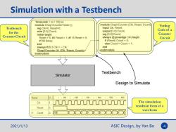
Simulation with a Testbench timescale 1 ns/100 ps module Chap1CounterTester ( module Chap1Counter(Clk,Reset,Count): input Clk,Reset: Verilog Testbench reg Clk=0,Reset=0; wire [3:0]Count; output [3:0]Count; Code of a for the Counter Circuit initial begin reg [3:0]Count; Counter Reset=0;#5 Reset=1;#115 Reset=0; always @(posedge Clk)begin Circuit #760 Sstop; if (Reset)Count 0; end else CountCount +1; always #26.5 Clk =Clk: end Chap1Counter U1 (CIk,Reset,Count); endmodule endmodule Testbench Simulator Design to Simulate Name 1,100.1·2001,300·1,4001.5001·600 Clk The simulation Reset results in form of a 0 waveform Count 80 3 2021/1/13 ASIC Design,by Yan Bo 4
ASIC Design, by Yan Bo Simulation with a Testbench Testbench for the Counter Circuit Verilog Code of a Counter Circuit `timescale 1 ns / 100 ps module Chap1CounterTester (); reg Clk=0, Reset=0; wire [3:0] Count; initial begin Reset = 0; #5 Reset = 1; #115 Reset = 0; #760 $stop; end always #26.5 Clk = ~ Clk; Chap1Counter U1 (Clk, Reset, Count); endmodule module Chap1Counter (Clk, Reset, Count); input Clk, Reset; output [3:0] Count; reg [3:0] Count; always @(posedge Clk) begin if (Reset) Count = 0; else Count = Count + 1; end endmodule Simulator Testbench Design to Simulate The simulation results in form of a waveform 2021/1/13 4
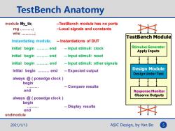
TestBench Anatomy module My_tb; --TestBench module has no ports reg.… --Local signals and constants 土 wire......... TestBench Module Instantiating module; -Instantiations of DUT initial begin .........end --Input stimuli:clock Stimulus Generater Apply Inputs initial begin .........end --Input stimuli:reset initial begin .........end --Input stimuli:other signals initial begin ........end --Expected output Design Module Design Under Test always @posedge clock begin --Compare results end Response Monitor Observe Outputs always @posedge clock begin -Display results end endmodule 2021/1/13 ASIC Design,by Yan Bo 5
ASIC Design, by Yan Bo TestBench Anatomy TestBench Module Design Module Stimulus Generater Apply Inputs Response Monitor Observe Outputs 2021/1/13 5 module My_tb; --TestBench module has no ports reg ……….; --Local signals and constants wire ……….; Instantiating module; -- Instantiations of DUT initial begin ……… end -- Input stimuli: clock initial begin ……… end -- Input stimuli: reset initial begin ……… end -- Input stimuli: other signals initial begin ……… end -- Expected output always @ ( posedge clock ) begin ……… -- Compare results end always @ ( posedge clock ) begin ……… -- Display results end endmodule Design Under Test
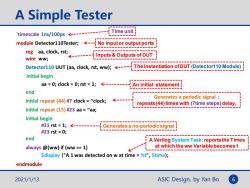
A Simple Tester Time unit timescale 1ns/100ps------- module Detector110Tester;--No inputor output ports reg aa,clock,rstiInputs&Outputs of DUT wire ww; Detector110 UUT (aa,clock,rst,ww);----The Instantiation ofDUT(Detector110 Module) initial begin aa =0;clock 0;rst =1;--------An initial statement end Generates a periodic signal initial repeat (44)#7 clock ~clock; ← repeats(44)times with(7time steps)delay, initial repeat (15)#23 aa ~aa; initial begin #31rst=1;<-------= Generates a no-periodic signal #23rst=0; end A Verilog System Task:reports the Times always @(ww)if (ww =1) at which the ww Variable becomes 1 Sdisplay ("A 1 was detected on w at time =%t",Stime); endmodule 2021/1/13 ASIC Design,by Yan Bo 6
ASIC Design, by Yan Bo A Simple Tester `timescale 1ns/100ps module Detector110Tester; reg aa, clock, rst; wire ww; Detector110 UUT (aa, clock, rst, ww); initial begin aa = 0; clock = 0; rst = 1; end initial repeat (44) #7 clock = ~clock; initial repeat (15) #23 aa = ~aa; initial begin #31 rst = 1; #23 rst = 0; end always @(ww) if (ww == 1) $display ("A 1 was detected on w at time = %t", $time); endmodule No input or output ports Inputs & Outputs of DUT The Instantiation of DUT (Detector110 Module) An initial statement Generates a periodic signal : repeats (44) times with (7time steps) delay, Generates a no-periodic signal A Verilog System Task: reports the Times at which the ww Variable becomes 1 Time unit 2021/1/13 6
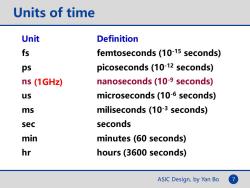
Units of time Unit Definition fs femtoseconds(10-15 seconds) ps picoseconds(10-12 seconds) ns (1GHz) nanoseconds(10-9 seconds) us microseconds(10-6 seconds) ms miliseconds (10-3 seconds) sec seconds min minutes(60 seconds) hr hours(3600 seconds) ASIC Design,by Yan Bo
ASIC Design, by Yan Bo 7 Units of time Unit Definition fs femtoseconds (10-15 seconds) ps picoseconds (10-12 seconds) ns nanoseconds (10-9 seconds) us microseconds (10-6 seconds) ms miliseconds (10-3 seconds) sec seconds min minutes (60 seconds) hr hours (3600 seconds) (1GHz)
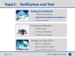
Topic3:Verification and Test Verilog for Testbench 。Testbench anatomy Behavioral modeling for Testbench 。Some examples Timing specification 。Delay model 。Timing verification 。Pipeline technology Design For Test(DFT) Test vs.Verification Build In Self Test (BIST) Scan and Boundary Scan 2021/1/13 ASIC Design,by Yan Bo 8
ASIC Design, by Yan Bo Topic3: Verification and Test Verilog for Testbench • Testbench anatomy • Behavioral modeling for Testbench • Some examples Timing specification • Delay model • Timing verification • Pipeline technology Design For Test (DFT) Test vs. Verification Build In Self Test (BIST) Scan and Boundary Scan 2021/1/13 8
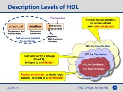
Description Levels of HDL Testbenches Formal documentation, 业 to communicate structural dataflow behavioral with other designers (sequential) Components and Concurrent interconnects statements 水 Subsetmostsuitable Registers State machines for synthesis一 Decoders HDL for Specification HDL for Simulation Test and verify a design (Feed it), to input to a simulator HDL for Synthesis (For Real Hardware) Realize and Iterate a digital logic design,to input to a synthesizer 2021/1/13 ASIC Design,by Yan Bo
ASIC Design, by Yan Bo 9 Description Levels of HDL HDL for Specification HDL for Simulation HDL for Synthesis (For Real Hardware) Formal documentation, to communicate with other designers Test and verify a design (Feed it), to input to a simulator Realize and Iterate a digital logic design, to input to a synthesizer 2021/1/13 Components and interconnects structural behavioral (sequential) Registers State machines Decoders Subset most suitable for synthesis Testbenches dataflow Concurrent statements
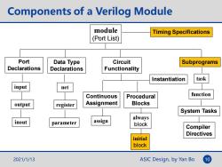
Components of a Verilog Module module Timing Specifications (Port List) Port Data Type Circuit Subprograms Declarations Declarations Functionality Instantiation task input net Continuous Procedural function output register Assignment Blocks System Tasks always inout parameter assign block Compiler Directives initial block 2021/1/13 ASIC Design,by Yan Bo 10
ASIC Design, by Yan Bo Components of a Verilog Module module (Port List) Port Declarations input output inout Data Type Declarations net register parameter Circuit Functionality Timing Specifications Continuous Assignment assign Procedural Blocks always block Subprograms task function System Tasks Compiler Directives Instantiation initial block 2021/1/13 10
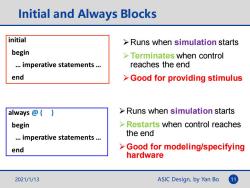
Initial and Always Blocks initial Runs when simulation starts begin >Terminates when control ..imperative statements... reaches the end end >Good for providing stimulus always Runs when simulation starts begin Restarts when control reaches ..imperative statements... the end end > Good for modeling/specifying hardware 2021/1/13 ASIC Design,by Yan Bo 11
ASIC Design, by Yan Bo Initial and Always Blocks initial begin … imperative statements … end always @ ( ) begin … imperative statements … end ➢Runs when simulation starts ➢Terminates when control reaches the end ➢Good for providing stimulus ➢Runs when simulation starts ➢Restarts when control reaches the end ➢Good for modeling/specifying hardware 2021/1/13 11
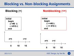
Blocking vs.Non-blocking Assignments Blocking (= Nonblocking (<= initial initial begin begin a=#5b; a<=#5b; c=#10d; C<=#10d; end end a=b c=d a=b c=d 5 10 15 5 10 15 2021/1/13 ASIC Design,by Yan Bo 12
ASIC Design, by Yan Bo Blocking vs. Non-blocking Assignments Blocking (=) Nonblocking (<=) initial begin a =#5 b; c =#10 d; end initial begin a <=#5 b; c <= #10 d; end 5 10 15 a=b c=d 5 10 15 a=b c=d 2021/1/13 12
按次数下载不扣除下载券;
注册用户24小时内重复下载只扣除一次;
顺序:VIP每日次数-->可用次数-->下载券;
- 电子科技大学:《ASIC设计 Application Specific Integrated Circuit Design》课程教学资源(课件讲稿)Topic 2.2 FPGA Design with Verilog(Supplementary).pdf
- 电子科技大学:《ASIC设计 Application Specific Integrated Circuit Design》课程教学资源(课件讲稿)Topic 2.1 FPGA Design with Verilog(FPGA Design Method、Design Examples).pdf
- 电子科技大学:《ASIC设计 Application Specific Integrated Circuit Design》课程教学资源(课件讲稿)Topic 1.3 Introduction-Our Course.pdf
- 电子科技大学:《ASIC设计 Application Specific Integrated Circuit Design》课程教学资源(课件讲稿)Topic 1.2 Introduction-ASIC Design.pdf
- 电子科技大学:《ASIC设计 Application Specific Integrated Circuit Design》课程教学资源(课件讲稿)Topic 1.1 Introduction-IC technology.pdf
- 电子科技大学:《现代网络理论与综合 Theory and Synthesize of Electric Network》课程教学资源(课件讲稿)第20讲 高阶有源滤波器.pdf
- 电子科技大学:《现代网络理论与综合 Theory and Synthesize of Electric Network》课程教学资源(课件讲稿)第19讲 有源滤波器.pdf
- 电子科技大学:《现代网络理论与综合 Theory and Synthesize of Electric Network》课程教学资源(课件讲稿)第9讲 信号流图分析法.pdf
- 电子科技大学:《现代网络理论与综合 Theory and Synthesize of Electric Network》课程教学资源(课件讲稿)第6讲 网络函数拓扑法.pdf
- 电子科技大学:《现代网络理论与综合 Theory and Synthesize of Electric Network》课程教学资源(课件讲稿)第5讲 不定导纳函数.pdf
- 电子科技大学:《现代网络理论与综合 Theory and Synthesize of Electric Network》课程教学资源(课件讲稿)第4讲 图论与电路方程.pdf
- 电子科技大学:《现代网络理论与综合 Theory and Synthesize of Electric Network》课程教学资源(课件讲稿)第3讲 图论.pdf
- 电子科技大学:《现代网络理论与综合 Theory and Synthesize of Electric Network》课程教学资源(课件讲稿)第18讲 电抗网络综合(电抗梯形滤波器综合).pdf
- 电子科技大学:《现代网络理论与综合 Theory and Synthesize of Electric Network》课程教学资源(课件讲稿)第17讲 无源双口网络参数(电抗二端口综合).pdf
- 电子科技大学:《现代网络理论与综合 Theory and Synthesize of Electric Network》课程教学资源(课件讲稿)第13讲 无源网络综合基础.pdf
- 电子科技大学:《现代网络理论与综合 Theory and Synthesize of Electric Network》课程教学资源(课件讲稿)第12讲 无源网络函数.pdf
- 电子科技大学:《现代网络理论与综合 Theory and Synthesize of Electric Network》课程教学资源(课件讲稿)第16讲 贝塞尔函数和频率变换.pdf
- 电子科技大学:《现代网络理论与综合 Theory and Synthesize of Electric Network》课程教学资源(课件讲稿)第15讲 滤波器逼近方法.pdf
- 电子科技大学:《现代网络理论与综合 Theory and Synthesize of Electric Network》课程教学资源(课件讲稿)第14讲 滤波器理论基础.pdf
- 电子科技大学:《现代网络理论与综合 Theory and Synthesize of Electric Network》课程教学资源(课件讲稿)第11讲 灵敏度分析(2/2).pdf
- 电子科技大学:《ASIC设计 Application Specific Integrated Circuit Design》课程教学资源(课件讲稿)Topic 4 VLSI for DSP.pdf
- 电子科技大学:《半导体封装测试与可靠性 Packaging,Testing and Reliability of Semiconductor》课程教学资源(教学大纲,思政版).pdf
- 电子科技大学:《半导体封装测试与可靠性 Packaging,Testing and Reliability of Semiconductor》课程教学资源(课件讲稿,思政版).pdf
- 电子科技大学:《电子无源元件工艺实验》课程实验课件讲稿 Electronic Passive Components Process Experiment Course(主讲:戴丽萍).pdf
- 电子科技大学:《DSP算法实现技术与架构 VLSI Digital Signal Processing Systems Design and Implementation》课程教学资源(教学大纲,凌翔).pdf
- 电子科技大学:《DSP算法实现技术与架构 VLSI Digital Signal Processing Systems Design and Implementation》课程教学资源(课件讲稿)Chapter 00 简介 Introduction to VLSI(凌翔).pdf
- 电子科技大学:《DSP算法实现技术与架构 VLSI Digital Signal Processing Systems Design and Implementation》课程教学资源(课件讲稿)Chapter 01 导论 Introduction to Digital Signal Processing Systems.pdf
- 电子科技大学:《DSP算法实现技术与架构 VLSI Digital Signal Processing Systems Design and Implementation》课程教学资源(课件讲稿)Chapter 02 迭代界 Iteration Bound.pdf
- 电子科技大学:《DSP算法实现技术与架构 VLSI Digital Signal Processing Systems Design and Implementation》课程教学资源(课件讲稿)Chapter 03 流水与并行 Pipelining and Parallel Processing.pdf
- 电子科技大学:《DSP算法实现技术与架构 VLSI Digital Signal Processing Systems Design and Implementation》课程教学资源(课件讲稿)Chapter 04 重定时 Retiming.pdf
- 电子科技大学:《DSP算法实现技术与架构 VLSI Digital Signal Processing Systems Design and Implementation》课程教学资源(课件讲稿)Chapter 05 展开 Unfolding.pdf
- 电子科技大学:《DSP算法实现技术与架构 VLSI Digital Signal Processing Systems Design and Implementation》课程教学资源(课件讲稿)Chapter 06 折叠 Folding.pdf
- 电子科技大学:《DSP算法实现技术与架构 VLSI Digital Signal Processing Systems Design and Implementation》课程教学资源(课件讲稿)Chapter 07 脉动阵列 Systolic Architecture.pdf
- 电子科技大学:《DSP算法实现技术与架构 VLSI Digital Signal Processing Systems Design and Implementation》课程教学资源(课件讲稿)Chapter 10 递归滤波器 Pipelined and Parallel Recursive and Adaptive Filters.pdf
- 电子科技大学:《DSP算法实现技术与架构 VLSI Digital Signal Processing Systems Design and Implementation》课程教学资源(课件讲稿)Chapter 08 快速卷积 Fast Convolution.pdf
- 电子科技大学:《DSP算法实现技术与架构 VLSI Digital Signal Processing Systems Design and Implementation》课程教学资源(课件讲稿)Chapter 09 算法强度缩减 Algorithmic strength reduction in filters and transforms.pdf
- 电子科技大学:《DSP算法实现技术与架构 VLSI Digital Signal Processing Systems Design and Implementation》课程教学资源(课件讲稿)Chapter 11 缩放噪声 Scaling and Roundoff Noise.pdf
- 电子科技大学:《DSP算法实现技术与架构 VLSI Digital Signal Processing Systems Design and Implementation》课程教学资源(课件讲稿)Chapter 13 位级运算 Bit-Level Arithmetic Architectures.pdf
- 电子科技大学:《DSP算法实现技术与架构 VLSI Digital Signal Processing Systems Design and Implementation》课程教学资源(课件讲稿)Chapter 14 冗余运算 Redundant Arithmetic.pdf
- 电子科技大学:《DSP算法实现技术与架构 VLSI Digital Signal Processing Systems Design and Implementation》课程教学资源(课件讲稿)Chapter 15 数字强度缩减 Numerical Strength Reduction.pdf
