《机械制造基础》课程教学课件(PPT讲稿)Fundamentals of Cutting
Chapter 1 Fundamentals of CuttingAbstract1.1 Basic definition2material of the cutting too上页下页退出2
Chapter 1 Fundamentals of Cutting Abstract 1.1 Basic definition 1.2 material of the cutting tool
AbsractTwo parts concerning the fundamental of metal cuttingprocess are involved in this chapter1 Basic definitionincluding basic concepts in cuttingprocess,such as cutting motions,parameters, referenceframe,marked angles, cutting layer parameters2 cutting tool materialincluding the necessaryperformance of cutting tool material(hardness, wearresistance,strength,toughness, hot hardness ...),two kinds ofnormal material for cutting tool(HSS and carbide alloy) andthe other material(coating,ceramics diamond and cubic boronNitride)下页上页退出
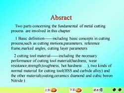
Two parts concerning the fundamental of metal cutting process are involved in this chapter 1 Basic definition——including basic concepts in cutting process,such as cutting motions,parameters, reference frame,marked angles, cutting layer parameters 2 cutting tool material——including the necessary performance of cutting tool material(hardness, wear resistance,strength,toughness, hot hardness .), two kinds of normal material for cutting tool(HSS and carbide alloy) and the other material(coating,ceramics diamond and cubic boron Nitride ) Absract
1. 1 Basic definition1.1.1 cutting motion and parameters?basic definition of the cutting regionexchange of the cutting angles1.1.4 work angles of the cutting tool1.1.5cutting layer parameters and mode上页下页退出二
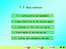
1.1 Basic definition 1.1.2 basic definition of the cutting region 1.1.3 exchange of the cutting angles 1.1.5 cutting layer parameters and mode 1.1.4 work angles of the cutting tool 1.1.1 cutting motion and parameters
1. 1. 1 cutting motions and parametersFor example,in turning,theworkpiece rotates,the cutting tool moveslongitudinally, the mixture of the two motions forms the external cylindricalsurface.There are three surfaces created in turn during the new surface isforming (Figurel.l):待加工表面Surfacetobemachined:meansthe已加工表面surfaceinwhichthematerialistoberemoved主运动Machining surface:means the surface isbeing machined by the cutting edge加工表面Machined surface:means the进给运动surfacein whichthematerial hasbeenremovedFig 1.lcuttingmotions in turning返回上页下页退出
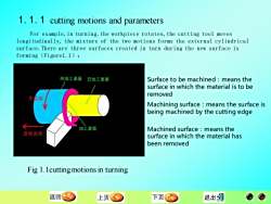
For example,in turning,the workpiece rotates,the cutting tool moves longitudinally, the mixture of the two motions forms the external cylindrical surface.There are three surfaces created in turn during the new surface is forming(Figure1.1): Fig 1.1cutting motions in turning Surface to be machined:means the surface in which the material is to be removed Machining surface:means the surface is being machined by the cutting edge Machined surface:means the surface in which the material has been removed 1.1.1 cutting motions and parameters
1.1.1.1cutting motionThebasic motion foramachinetoolincludeslinearmotion androtationalmotion.If classified accordingtothefunctions of thecuttingtool inrelation withtheworkpiece,theyarecalledthemainmotionandthefeedmotion,shownasFigi1(1)themainmotionthemainmotionreguiredtoremovethemetal.Usuallyithasthebiggestvelocity,andconsumesmostofthepower(2)thefeedmotionIt brings the new metal into cuttingconstantly.It can be continuousorinterrupted上页下页退出
1.1.1.1 cutting motion The basic motion for a machine tool includes linear motion and rotational motion. If classified according to the functions of the cutting tool in relation with the workpiece, they are called the main motion and the feed motion,shown as Fig.1.1 (1)the main motion the main motion required to remove the metal. Usually it has the biggest velocity, and consumes most of the power (2) the feed motion It brings the new metal into cutting constantly. It can be continuous or interrupted
(3) resultant motion and velocityWhenthemain motion and thefeed motiontakepart incuttingsimultaneously,the velocityin one pointof thecuttingedge relativetotheworkpieceis calledresultantcuttingmotion,its sizeanddirectioncanberepresentedwithavectorVe,shownasFigl3,anditequalsthevectorsum ofthetwomotions(1.1)Ve=Ve+Vf上页下页退出址
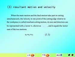
When the main motion and the feed motion take part in cutting simultaneously, the velocity in one point of the cutting edge relative to the workpiece is called resultant cutting motion, its size and direction can be represented with a vector ve, shown as Fig.1.3, and it equals the vector sum of the two motions ve=vc+vf (1.1) (3)resultant motion and velocity
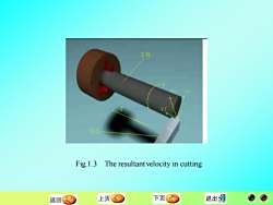
Fig.1.3 The resultantvelocity in cutting上页下页退出S返回
Fig.1.3 The resultant velocity in cutting
1.1.1.2 Three elements in cuttingVefapare calledthethreeelements incutting(1)CuttingspeedMost ofthe main cutting motions are rotational motion.Thevelocityinonepointoftherotatingbody(cuttingtoolorworkpiece)canbecalculatedusingthefollowingformuladn m/s or m/min(1.2)Vc=1000where d-the rotational diameter of one point in the workpiece or the cutting tool (mm)nnumberofrevolutionpersecondorperminute(r/sorr/min).(r/sorr/min)上页下页退出
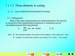
1.1.1.2 Three elements in cutting ve、f 、 ap are called the three elements in cutting 1000 dn (1)Cutting speed Most of the main cutting motions are rotational motion.The velocity in one point of the rotating body(cutting tool or workpiece) can be calculated using the following formula vc= m/s or m/min (1.2) where d-the rotational diameter of one point in the workpiece or the cutting tool(mm) n-number of revolution per second or per minute (r/s or r/min). (r/s or r/min)

(2)Feedingspeed,feedandfeedpertoothFeeding speed y,isthefeed inaunittime (m/s orm/min)Feed is the relative displacement between the workpiece and the cutter along thedirectionoffeedingmotionperrevolutionorperstock(mm/r)。For multipleteeth cutting tools, such as milling cutter,reamer, broach, gear hob etcfeedfzmaybemeasured inmillimeters pertooltooth (mm/z).Obviously,(1.3)v-fn=fzznmm/s or mm/min上页下页退出式
Feeding speed vf is the feed in a unit time (m/s or m/min) Feed is the relative displacement between the workpiece and the cutter along the direction of feeding motion per revolution or per stock (mm/r)。 For multiple teeth cutting tools, such as milling cutter, reamer, broach, gear hob etc. feed fz may be measured in millimeters per tool tooth (mm/z). Obviously, vf=f·n=fz·z·n mm/s or mm/min (1.3) (2) Feeding speed, feed and feed per tooth
(3) Back engagement of the cutting edgeFor turningand planing,the back engagement ofthecuttingedge a,isequal to the normal distancebetween the machined surface and the workpiecesurfacetobecut(mm).Forcylindrical turning,(1.4)ap=(dw-dm)/2mmFordrillingap=dm/2(1.5)mmwheredmdiameter of machined surface (mm)dwdiameterofworkpiece surfacetobecut (mm)上页下页退出
(3)Back engagement of the cutting edge For turning and planing, the back engagement of the cutting edge ap is equal to the normal distance between the machined surface and the workpiece surface to be cut(mm). For cylindrical turning, ap =(dw-dm)/2 mm (1.4) For drilling ap =dm/2 mm (1.5) where dm——diameter of machined surface(mm) dw——diameter of workpiece surface to be cut(mm)
按次数下载不扣除下载券;
注册用户24小时内重复下载只扣除一次;
顺序:VIP每日次数-->可用次数-->下载券;
- 《机械制造基础》课程教学课件(PPT讲稿)金属切削加工的基础知识.ppt
- 《机械制造基础》课程教学课件(PPT讲稿)先进加工工艺及设备.ppt
- 《机械制造基础》课程教学课件(PPT讲稿)机械制造技术的发展.ppt
- 《机械制造基础》课程教学课件(PPT讲稿)工件在加工时的定位.ppt
- 《机械制造基础》课程教学课件(PPT讲稿)工程材料篇(双语).ppt
- 《机械制造基础》课程教学课件(PPT讲稿)定位基准的选择 Selection of Location Datum.ppt
- 《机械制造基础》课程教学课件(PPT讲稿)特殊形状表面的加工.ppt
- 《机械制造基础》课程教学课件(PPT讲稿)金属的塑性变形.ppt
- 《机械制造基础》课程教学课件(PPT讲稿)纳米技术.ppt
- 《机械制造基础》课程教学课件(PPT讲稿)神奇的纳米材料.ppt
- 《机械制造基础》课程教学课件(PPT讲稿)纳米科技.ppt
- 《机械制造基础》课程教学课件(PPT讲稿)工程材料的性能.ppt
- 《机械制造基础》课程教学课件(PPT讲稿)机械加工工艺概论.ppt
- 《机械制造基础》课程教学资源(试卷习题)机械加工习题(答案).doc
- 《机械制造基础》课程教学资源(试卷习题)机械加工习题(试题).doc
- 《机械制造基础》课程教学资源(试卷习题)材料成型综合习题(答案).doc
- 《机械制造基础》课程教学资源(试卷习题)材料成型综合习题(试题).doc
- 《机械制造基础》课程教学资源(授课教案,石河子大学:胡蓉).doc
- 《机械制造基础》课程教学资源(授课教案)机制基础(下)教案.doc
- 《机械制造基础》课程教学资源(授课教案)机制基础(上)教案.doc
- 《机械制造基础》课程教学课件(PPT讲稿)尺寸公差——几何量公差与检测(概述、孔、轴公差配合).ppt
- 《机械制造基础》课程教学课件(PPT讲稿)锻造.ppt
- 《机械制造基础》课程教学课件(PPT讲稿)铸造.ppt
- 《机械制造基础》课程教学课件(PPT讲稿)工程材料——钢的热处理.ppt
- 《机械制造基础》课程教学课件(PPT讲稿)焊接(热加工).ppt
- 《数字化测图原理与方法》课程教学大纲 The principle and method of digital mapping.doc
- 《数字化测图原理与方法》课程作业习题(无答案)第一章 绪论.doc
- 《数字化测图原理与方法》课程作业习题(无答案)第三章 全站仪及其应用.doc
- 《数字化测图原理与方法》课程作业习题(无答案)第二章 数字测图系统的组成习题.doc
- 《数字化测图原理与方法》课程作业习题(无答案)第五章 CASS 7.0测图系统的使用.doc
- 《数字化测图原理与方法》课程作业习题(无答案)第六章 地形图数字化.doc
- 《数字化测图原理与方法》课程作业习题(无答案)第四章 数字测图外业.doc
- 《数字化测图原理与方法》课程教学资源(实验指导)实验一 全站仪认识和使用.doc
- 《数字化测图原理与方法》课程教学资源(实验指导)实验三 野外数据采集.doc
- 《数字化测图原理与方法》课程教学资源(实验指导)实验二 全站仪导线测量.doc
- 《数字化测图原理与方法》课程教学资源(实验指导)实验五 扫描矢量数字化方法.doc
- 《数字化测图原理与方法》课程教学资源(实验指导)实验四 数字测图内业成图方法 指导书.doc
- 《数字化测图原理与方法》课程教学资源(教案讲义)第三章 数字化地形图的测绘.doc
- 《数字化测图原理与方法》课程教学资源(教案讲义)第二章 控制测量.doc
- 《数字化测图原理与方法》课程教学资源(教案讲义)第一章 数字化测图绪钟来星.doc
