《信号与系统》课程教学资源(MATLAB教程)第六章 Simulink 基础
第六章Simulink基础 Chapter 6:Introduction to Simulink 一.Simulink初步(Primer of Simulink) MATLAB Simulink是一个动态仿真系统,用于对动态系统进行仿真和 分析,预先模拟实际系统的特性和响应,根据设计和使用要求,对系统进行 修改和优化。 Simulink提供了图形化用户界面,只须点击鼠标就可以轻易的完成模型 的创建、调试和仿真工作,用户不须专门掌握一种程序设计语言。 Simulink可将系统分为从高级到低级的几个层次,每层又可以细分为几 个部分,每层系统构建完成后,将各层连接起来构成一个完整系统。 模型创建完成后,可以启动系统的仿真功能分析系统的动态特性,其内 置的分析工具包括各种仿真算法、系统线性化、寻求平衡点等。仿真结果可 以以图形方式在示波器窗口显示,也可将输出结果以变量形式保存起来,并 输入到MATLAB中以完成进一步的分析。 Simulink可以仿真线性和非线性系统,并能创建连续时间、离散时间或 二者混合的系统。支持多采样频率系统。 Simulink Version 6.0(R14)05-May-2004 Model analysis and construction functions. Simulation sim Simulate a Simulink model sldebug -Debug a Simulink model. simset Define options to SIM Options structure. simget Get SIM Options structure Linearization and trimming. linmod Extract linear model from continuous-time system. linmod2 -Extractlinear model,advanced method. dlinmod -Extract linear model from discrete-time system
第六章 Simulink 基础 Chapter 6: Introduction to Simulink 一.Simulink 初步(Primer of Simulink) MATLAB Simulink 是一个动态仿真系统,用于对动态系统进行仿真和 分析,预先模拟实际系统的特性和响应,根据设计和使用要求,对系统进行 修改和优化。 Simulink 提供了图形化用户界面,只须点击鼠标就可以轻易的完成模型 的创建、调试和仿真工作,用户不须专门掌握一种程序设计语言。 Simulink 可将系统分为从高级到低级的几个层次,每层又可以细分为几 个部分,每层系统构建完成后,将各层连接起来构成一个完整系统。 模型创建完成后,可以启动系统的仿真功能分析系统的动态特性,其内 置的分析工具包括各种仿真算法、系统线性化、寻求平衡点等。仿真结果可 以以图形方式在示波器窗口显示,也可将输出结果以变量形式保存起来,并 输入到 MATLAB 中以完成进一步的分析。 Simulink 可以仿真线性和非线性系统,并能创建连续时间、离散时间或 二者混合的系统。支持多采样频率系统。 Simulink Version 6.0 (R14) 05-May-2004 Model analysis and construction functions. Simulation sim - Simulate a Simulink model. sldebug - Debug a Simulink model. simset - Define options to SIM Options structure. simget - Get SIM Options structure Linearization and trimming. linmod - Extract linear model from continuous-time system. linmod2 - Extract linear model, advanced method. dlinmod - Extract linear model from discrete-time system
trim Find steady-state operating point. Model Construction. close system -Close open model or block. new_system -Create new empty model window. open_system -Open existing model or block. load_system Load existing model without making model visible. save_system -Save an open model add_block -Add new block. add line -Add new line. delete_block -Remove block. delete line Remove line. find_system -Search a model. hilite system -Hilite objects within a model. replace block -Replace existing blocks with a new block. set_param -Set parameter values for model or block. get_param -Get simulation parameter values from model. add param Add a user-defined string parameter to a model delete_param Delete a user-defined parameter from a model bdclose Close a Simulink window. bdroot -Rootlevel model name. gcb Get the name of the current block. gcbh Get the handle of the current block. ges Get the name of the current system. getfullname get the full path name of a block slupdate Update older 1.x models to 3.x. addterms -Add terminators to unconnected ports. boolean -Convert numeric array to boolean slhelp Simulink user's guide or block help
trim - Find steady-state operating point. Model Construction. close_system - Close open model or block. new_system - Create new empty model window. open_system - Open existing model or block. load_system - Load existing model without making model visible. save_system - Save an open model. add_block -Add new block. add_line - Add new line. delete_block - Remove block. delete_line - Remove line. find_system - Search a model. hilite_system - Hilite objects within a model. replace_block - Replace existing blocks with a new block. set_param - Set parameter values for model or block. get_param - Get simulation parameter values from model. add_param - Add a user-defined string parameter to a model. delete_param - Delete a user-defined parameter from a model. bdclose - Close a Simulink window. bdroot - Root level model name. gcb - Get the name of the current block. gcbh - Get the handle of the current block. gcs - Get the name of the current system. getfullname - get the full path name of a block slupdate - Update older 1.x models to 3.x. addterms -Add terminators to unconnected ports. boolean - Convert numeric array to boolean. slhelp - Simulink user's guide or block help

Masking. hasmask -Check for mask. hasmaskdlg Check for mask dialog hasmaskicon -Check for mask icon. iconedit -Design block icons using ginput function. maskpopups -Return and change masked block's popup menu items. movemask Restructure masked built-in blocks as masked subsystems. Library. libinfo Get library information for a system. Diagnostics. sllastdiagnostic-Last diagnostic array. sllasterror Last error array. sllastwarning Last warning array. sldiagnostics Get block count and compile stats for a model. Hardcopy and printing frameedit Edit print frames for annotated model printouts. print Print graph or Simulink system;or save graph to M-file. printopt -Printer defaults. orient -Set paper orientation. simulink is both a directory and a function. Copyright 1990-2004 The Math Works,Inc. Simulink的三大步骤(procedure of Simulink):
Masking. hasmask - Check for mask. hasmaskdlg - Check for mask dialog. hasmaskicon - Check for mask icon. iconedit - Design block icons using ginput function. maskpopups - Return and change masked block's popup menu items. movemask - Restructure masked built-in blocks as masked subsystems. Library. libinfo - Get library information for a system. Diagnostics. sllastdiagnostic - Last diagnostic array. sllasterror - Last error array. sllastwarning - Last warning array. sldiagnostics - Get block count and compile stats for a model. Hardcopy and printing. frameedit - Edit print frames for annotated model printouts. print - Print graph or Simulink system; or save graph to M-file. printopt - Printer defaults. orient - Set paper orientation. simulink is both a directory and a function. Copyright 1990-2004 The MathWorks, Inc. Simulink 的三大步骤(procedure of Simulink):
模型创建与定义、(Model creating and definition) 模型的分析、(Model analyzing 模型的修正。(Model modifying) 模型构建 和定义 模型的分析 Simulink的运行:(Running of Simulink) l、运行Simulink:命令窗口下点击Simulink图标(或键入Simulink命 令)→Simulink Library Browser(浏览器)→simulink树状列表形 式的模块库(包含simulink模块库中的各种模块及其它Toolbox和 Blockset中的模块) 2、选择建模模块:展开树状列表,用鼠标点击所需类别的模块项,所 选模块类的具体模块库就在右侧的列表框中显示出来,提供建模使用。 也可以在在输入栏中键入模块名并点击ind按钮进行查询。 3、打开模型创建窗口:(open the window of mode creating)。 在工具栏中选择“建立新模型”的图标,弹出名为Untitled的空白窗口, 选择Ope窗口可以打开存于硬盘中已建的模型,完成模型的运行或修 改。 二.Simulink的基本模块(basic module) simulink浏览器窗口左侧的simulink项上单击鼠标右键,弹出菜单 “Open the Simulink'Labrary'”选项,将打开simulink模块库窗口。 1.信号源模块:source,棋块及功能见(表8-1) 2.输出模块:Sinks,模块及功能见(表8-2)
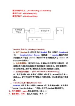
模型创建与定义、( Model creating and definition) 模型的分析、(Model analyzing) 模型的修正。(Model modifying) Simulink 的运行:(Running of Simulink) 1、运行 Simulink:命令窗口下点击 Simulink 图标(或键入 Simulink 命 令)→ Simulink Library Browser(浏览器)→ simulink 树状列表形 式的模块库(包含 simulink 模块库中的各种模块及其它 Toolbox 和 Blockset 中的模块) 2、选择建模模块:展开树状列表,用鼠标点击所需类别的模块项, 所 选模块类的具体模块库就在右侧的列表框中显示出来,提供建模使用。 也可以在在输入栏中键入模块名并点击 Find 按钮进行查询。 3、打开模型创建窗口:(open the window of mode creating)。 在工具栏中选择“建立新模型”的图标,弹出名为 Untitled 的空白窗口, 选择 Open 窗口可以打开存于硬盘中已建的模型,完成模型的运行或修 改。 二.Simulink 的基本模块(basic module) simulink 浏览器窗口左侧的 simulink 项上单击鼠标右键,弹出菜单 “Open the ‘Simulink’Labrary’”选项,将打开 simulink 模块库窗口。 1.信号源模块:source,模块及功能见(表 8—1) 2.输出模块:Sinks, 模块及功能见(表 8—2) 模型构建 和定义 模型的分析 显 示 修 正
3.连续系统模块:Continuous,模块及功能见(表8一3) 4.离散系统模块:Discrete,模块及功能见(表8一4) 5.数学运算模块:Math,模块及功能见(表8一5) 6.函数和表模块:Function&Tables,模块及功能见(表86) 7.非线性系统模块:Nonlinear,模块及功能见(表87) 8.信号与系统模块:Signal&Systems,模块及功能见(表88) 三.Simulink建模(Simulinc module creating) L.模块的创建与操作(Creatingand operation of Simulink) (I)创建模块:(module creating) (1)在浏览器列表中点击需要的模块,按住鼠标左键并拖曳至模型窗口 即可。 (2)双击模块可在弹出的对话框中修改相应的模块参数 (3)在模块下方名称处双击可改变模块名称。 (2)模块操作(module operation) (a)模块的选择(module selection) (b)移动模块(module moving) (c)模块的缩放(modulee sealing) (d)复制模块:(module copy) 四种方法: 大在选定模块处,按下鼠标右键并拖动至适当位置: *选定模块,在工具栏中(或Edit菜单中)选中Copy与Paste按 钮; *在选定的模块处点击鼠标右键,在弹出的菜单中选择C0py与 Paste选项; +按住”Ct”键,按下鼠标左键,将选定的模块拖至适当的位置。 (e)模块的旋转与翻转:(Rotating and turnover of module) 旋转:(rotate)将鼠标指向要翻转的模块并按下鼠标右键,选择弹出菜单 中的Format栏中的Rotate项,模块顺时针旋转90°。 翻转:将鼠标指向要翻转的模块并按下鼠标右键,选择弹出菜单中的 Format栏中的Flip Block项,模块顺时针旋转180
3. 连续系统模块: Continuous, 模块及功能见(表 8—3) 4. 离散系统模块:Discrete, 模块及功能见(表 8—4) 5. 数学运算模块:Math, 模块及功能见(表 8—5) 6.函数和表模块: Function & Tables, 模块及功能见(表 8—6) 7. 非线性系统模块:Nonlinear, 模块及功能见(表 8—7) 8. 信号与系统模块:Signal & Systems, 模块及功能见(表 8—8) 三. Simulink 建模(Simulinc module creating) 1. 模块的创建与操作(Creating and operation of Simulink) (1) 创建模块:(module creating) (1)在浏览器列表中点击需要的模块,按住鼠标左键并拖曳至模型窗口 即可。 (2)双击模块可在弹出的对话框中修改相应的模块参数 (3)在模块下方名称处双击可改变模块名称。 (2)模块操作(module operation) (a)模块的选择(module selection) (b)移动模块 (module moving) (c)模块的缩放(modulee scaling) (d) 复制模块:(module copy) 四种方法: * 在选定模块处,按下鼠标右键并拖动至适当位置; * 选定模块,在工具栏中(或 Edit 菜单中)选中 Copy 与 Paste 按 钮; * 在选定的模块处点击鼠标右键,在弹出的菜单中选择 Copy 与 Paste 选项; * 按住”Ctrl”键,按下鼠标左键,将选定的模块拖至适当的位置。 (e)模块的旋转与翻转:(Rotating and turnover of module) 旋转:(rotate)将鼠标指向要翻转的模块并按下鼠标右键,选择弹出菜单 中的 Format 栏中的 Rotate 项,模块顺时针旋转90o。 翻转:将鼠标指向要翻转的模块并按下鼠标右键,选择弹出菜单中的 Format 栏中的 Flip Block 项,模块顺时针旋转 180o
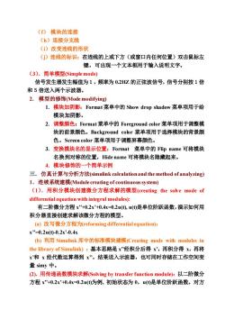
()模块的连接 (h)连接分支线 ()改变连线的形状 ()连线的标识:在连线的上或下方(或窗口内任何位置)双击鼠标左 键,可出现一个文本框用于输入说明文字。 (3).简单模型(Simple mode) 信号发生器发生幅值为1,频率为0.2HZ的正弦波信号,信号分别按1倍 和5倍送入两个示波器。 2.模型的修饰Mode modifying) 1.模块加阴影:Format菜单中的Show drop shadow菜单项用于给 模块加阴影。 2.调整颜色:Format3菜单中的Foreground color菜单项用于调整模 块的前景颜色。Background color菜单项用于选择模块的背景颜 色。Screen color菜单项用于调整屏幕颜色。 3.变换模块名的显示位置:Format菜单中的Flip name可将模块 名换到对称的位置,Hide name可将模块名隐藏起来。 4.模块修饰的一个简单示例 三.仿真计算与分析方法((simulink calculation and the method of analyzing) 1.连续系统建模(Module creating of continuous system) (I).用积分模块创建微分方程求解的模型(creating the solve mode of differential equation with integral modules): 有二阶微分方程x”+0.2x'0.4x=0.2u(),u()是单位阶跃函数,演示如何用 积分器直接创建求解该微分方程的模型。 (a)改写微分方程为reforming differential equation): x”=0.2u(0-0.2x'-0.4x b)利用Simulink库中的标准模块建模(Creating mode with modules in the library of Simulink):基本思路是x”经积分后得x',再积分得x,再将 x和x经代数运算得到x”。结果送入示波器,也可同时存储在工作空间变 量simy中。 (2).用传递函数模块求解(Solving by transfer function module):以二阶微分 方程x”+0.2x'+0.4x0.2u()为例,初始状态为0,u()是单位阶跃函数。对方
(f) 模块的连接 (h)连接分支线 (i)改变连线的形状 (j)连线的标识:在连线的上或下方(或窗口内任何位置)双击鼠标左 键,可出现一个文本框用于输入说明文字。 (3).简单模型(Simple mode) 信号发生器发生幅值为1,频率为 0.2HZ 的正弦波信号,信号分别按1倍 和5倍送入两个示波器。 2. 模型的修饰(Mode modifying) 1. 模块加阴影:Format 菜单中的 Show drop shadow 菜单项用于给 模块加阴影。 2. 调整颜色:Format 菜单中的 Foreground color 菜单项用于调整模 块的前景颜色。Background color 菜单项用于选择模块的背景颜 色。Screen color 菜单项用于调整屏幕颜色。 3. 变换模块名的显示位置:Format 菜单中的 Flip name 可将模块 名换到对称的位置,Hide name 可将模块名隐藏起来。 4. 模块修饰的一个简单示例 三.仿真计算与分析方法(simulink calculation and the method of analyzing) 1.连续系统建模(Module creating of continuoussystem) (1).用积分模块创建微分方程求解的模型(creating the solve mode of differential equation with integral modules): 有二阶微分方程 x’’+0.2x’+0.4x=0.2u(t), u(t)是单位阶跃函数,演示如何用 积分器直接创建求解该微分方程的模型。 (a) 改写微分方程为(reforming differential equation): x’’=0.2u(t)-0.2x’-0.4x (b) 利用 Simulink 库中的标准模块建模(Creating mode with modules in the library of Simulink) :基本思路是 x’’经积分后得 x’,再积分得 x,再将 x’和 x 经代数运算得到 x’’。结果送入示波器,也可同时存储在工作空间变 量 simy 中。 (2).用传递函数模块求解(Solving by transfer function module):以二阶微分 方程 x’’+0.2x’+0.4x=0.2u(t)为例, 初始状态为 0,u(t)是单位阶跃函数。对方
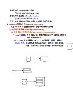
程两边进行Laplace变换,得到: s2X(s)+0.2sX(s)+0.4X(s-0.2U(s) 整理后得传递函数:(Transfer function) Gs)-X(s/U(s-0.2/s2+0.2s+0.4) 利用上式采用传递函数模块可建立求解徽分方程的模型。 2.Simulink结果的分析(Analyzing of the results): 执行simulink后检查输出结果并做进一步的分析与判断。 ()输出信号的观察(output signalobservation) (a将信号输出到显示模块(Export signal to display module) *Scop(示波器):将信号显示在示波器的独立窗口中,通过双击模块即 可打开示波器模块。 *XY Graph显示器模块:在MATLAB图形窗口绘制二维图形, Display模块:将结果以数字形式显示出来,在模块中直接滚动显 标量、矢量和矩阵形式得结果输出窗口结构略有不 24151 2415
程两边进行 Laplace 变换,得到: s 2X(s)+0.2sX(s)+0.4X(s)=0.2U(s) 整理后得传递函数:(Transfer function) G(s)=X(s)/U(s)=0.2/(s2+0.2s+0.4) 利用上式采用传递函数模块可建立求解微分方程的模型。 2. Simulink 结果的分析(Analyzing of the results): 执行 simulink 后检查输出结果并做进一步的分析与判断。 (1) 输出信号的观察(output signal observation) (a) 将信号输出到显示模块(Export signal to display module) * Scope(示波器):将信号显示在示波器的独立窗口中,通过双击模块即 可打开示波器模块。 * XY Graph 显示器模块:在 MATLAB 图形窗口绘制二维图形, * Display 模块:将结果以数字形式显示出来,在模块中直接滚动显示。 标量、矢量和矩阵形式得结果输出窗口结构略有不同
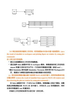
【12345 Reshape Reshape (b)将仿真结果存储到工作空间,再用绘图命令在命令窗口绘制图形,(v the result of simulink to workspace and plotting figure on window by using plot command) 有三种方法可供选择: *通过示波器模块向工作空间存储数据; *通过选择Sinksi函数库中的To workspace模块,将数据保存到工作空间的 simout变量中,同时还可以产生一个存放时间数据的变量(缺省tout); *通过Simulation莱单选择Simulation Paremeter菜单项中的WorkspaceI/O 页,根据各个参数的选择来确定存储的数据内容的类型。 (C),将仿真结果通过输出端口返回到MATLAB命令窗口,再利用绘图命令绘 出输出图形(return the result of simulink from export to MATLAB window and then drawing the plot on window by using plot command): 在Sinks函数库中有一个名为Outl的模块,将数据输入到这个模块,该模 块就会将数据输出到MATLAB命令窗口,并用名为yout的变量保存,同时 还将时间数据用tout变量保存。 存储在工作空间的结果可以进行进一步的分析
(b)将仿真结果存储到工作空间,再用绘图命令在命令窗口绘制图形,(save the result of simulink to workspace and plotting figure on window by using plot command) 有三种方法可供选择: * 通过示波器模块向工作空间存储数据; * 通过选择 Sinks 函数库中的 To workspace 模块,将数据保存到工作空间的 simout 变量中,同时还可以产生一个存放时间数据的变量(缺省 tout); *通过 Simulation 菜单选择 Simulation Paremeter 菜单项中的 WorkspaceI/O 页,根据各个参数的选择来确定存储的数据内容的类型。 (c). 将仿真结果通过输出端口返回到 MATLAB 命令窗口,再利用绘图命令绘 出输出图形 (return the result of simulink from export to MATLAB window and then drawing the plot on window by using plot command) : 在 Sinks 函数库中有一个名为 Out1 的模块,将数据输入到这个模块,该模 块就会将数据输出到 MATLAB 命令窗口,并用名为 yout 的变量保存,同时 还将时间数据用 tout 变量保存。 存储在工作空间的结果可以进行进一步的分析
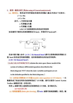
2.使用一般的分析工具(the using of General analysis tool) ().线性化:将状态空间所描述的线性系统输入输出关系由下式表示: x'=Ax+Bu y=Cx+Du 其中:x代表状态矢量 y代表输出矢量 u代表输入矢量 A,B,C,D为系统线性化的状态空间矩阵 如创建用于线性化的系统模型名为lmod,并保存为”1mod.md” + 在命令窗口输入命令ABCD=-linmod(Imod')就可以获得系统的常微分方 程mod的状态空间线性模型,返回系统线性化的状态空间矩阵。 [A B C D]=linmod('Imod') ([A,B,C,D]=LINMOD('SYS)obtains the state-space linear model of the system of ordinary differential equations described in the block diagram'SYS'when the state variables and inputs are set to the defaults specified in the block diagram.) (b)由状态方程转成LTI对象(transfer state equations to LTI object):一旦 数据形成了状态空间形式或者转变成了LTI对象,就可以使用Control System Toolbox函数进行进一步的分析。 利用ss函数可将上面线性化的系统转成LTI对象,命令格式为: sys=ss(A,B,C,D) (c)绘制波德图:(Bode plot drawing)用bode函数可绘制波德图,(相位、幅
2 Out2 1 Out1 2 s+1 Transfer Fcn1 2 -s +s+1 2 Transfer Fcn Add 1 In1 2.使用一般的分析工具(the using of General analysis tool) (a). 线性化:将状态空间所描述的线性系统输入输出关系由下式表示: x’=Ax+Bu y=Cx+Du 其中:x 代表状态矢量 y 代表输出矢量 u 代表输入矢量 A,B,C,D 为系统线性化的状态空间矩阵 如创建用于线性化的系统模型名为 lmod,并保存为”lmod.mdl”. 在命令窗口输入命令 [A B C D]=linmod(‘lmod’)就可以获得系统的常微分方 程 lmod 的状态空间线性模型,返回系统线性化的状态空间矩阵。 [A B C D]=linmod(‘lmod’) ([A,B,C,D]=LINMOD('SYS') obtains the state-space linear model of the system of ordinary differential equations described in the block diagram 'SYS' when the state variables and inputs are set to the defaults specified in the block diagram.) (b)由状态方程转成 LTI 对象(transfer state equations to LTI object):一旦 数据形成了状态空间形式或者转变成了 LTI 对象,就可以使用 Control System Toolbox 函数进行进一步的分析。 利用 ss 函数可将上面线性化的系统转成 LTI 对象,命令格式为: sys=ss(A,B,C,D) (c) 绘制波德图:(Bode plot drawing) 用 bode 函数可绘制波德图,(相位、幅
值与频率的关系图) bode(A,B,C,D)bode(sys) BODE(SYS)draws the Bode plot of the LTI model SYS(created with either TF ZPK,SS,or FRD).The frequency range and number of points are chosen automatically (d)线性时间响应Linear time response)片 给一个阶跃信号(step signal):step(A,B,C,D)或step(sys)线性化阶响应 或给一个脉冲信号(impulse:)impulse(A,B,C,D)或impulse(ys)线性化脉 冲响应 (c)求系统平衡点(find the balance point of system):在非线性系统中,分析评 估系统稳定性或稳定状态时大多需要用到平衡点。平衡点是指所有状态导数等 于零的点。若仅有部分状态导数等于零,则称为偏平衡点。 要使输出为1,并找出输入以及状态值时,可用”tmim”函数来实现。 以前面创建的1mod模型为例: %第一步:对状态变量x以及输入Ⅱ做初步设定,并设定想要的输出值。 x=0:0:0: 1=0; y=1;1 %第二步:使用索引变量确定那些值可变,那些是固定不变的。 ix=;%任何状态值可变 iu=] %任何输入可变 iy=1,2引;%两个输出不能变 %第三步:调用trim函数,求出系统平衡点。 [x,u,y,dx]=trim('Imod',x,u,y,ix,iu,iy) IA,B,C,D=LINMOD(Imod)%系统线性化的状态空间矩阵 sys=ss(A,B,C,D) %由状态方程转成LTI对象 figure(1) bode(sys) %绘制波德图,(相位、幅值与频率的关系图) figure(2)
值与频率的关系图) bode(A,B,C,D) 或 bode(sys) BODE(SYS) draws the Bode plot of the LTI model SYS (created with either TF, ZPK, SS, or FRD). The frequency range and number of points are chosen automatically. (d)线性时间响应(Linear time response): 给一个阶跃信号(step signal):step(A,B,C,D) 或 step(sys) 线性化阶响应 或给一个脉冲信号(impulse):impulse(A,B,C,D) 或 impulse(sys)线性化脉 冲响应 (e)求系统平衡点(find the balance point of system):在非线性系统中,分析评 估系统稳定性或稳定状态时大多需要用到平衡点。平衡点是指所有状态导数等 于零的点。若仅有部分状态导数等于零,则称为偏平衡点。 要使输出为 1,并找出输入以及状态值时,可用”trim”函数来实现。 以前面创建的”lmod”模型为例: %第一步:对状态变量 x 以及输入 u 做初步设定,并设定想要的输出值。 x=[0;0;0]; u=0; y=[1;1]; %第二步:使用索引变量确定那些值可变,那些是固定不变的。 ix=[ ]; %任何状态值可变 iu=[ ]; %任何输入可变 iy=[1,2]; %两个输出不能变 %第三步:调用 trim 函数,求出系统平衡点。 [x,u,y,dx]=trim(‘lmod’,x,u,y,ix,iu,iy) [A,B,C,D]=LINMOD('lmod') %系统线性化的状态空间矩阵 sys=ss(A,B,C,D) %由状态方程转成 LTI 对象 figure(1) bode(sys) %绘制波德图,(相位、幅值与频率的关系图) figure(2)
按次数下载不扣除下载券;
注册用户24小时内重复下载只扣除一次;
顺序:VIP每日次数-->可用次数-->下载券;
- 《信号与系统》课程教学资源(MATLAB教程)第五章 图形处理功能.doc
- 《信号与系统》课程教学资源(MATLAB教程)第二章 MATLAB程序设计基础.doc
- 《信号与系统》课程教学资源(MATLAB教程)第三章 MATLAB的数值计算功能.doc
- 《信号与系统》课程教学资源(MATLAB教程)第七章 MATLAB的GUI 程序设计.doc
- 《信号与系统》课程教学资源(MATLAB教程)第一章 MATLAB 入门.doc
- 《信号与系统》课程教学资源(书籍文献)信号处理与线性系统(英)B.P.Lathi, Signal Processing and Linear Systems.pdf
- 《信号与系统》课程教学资源(书籍文献)信号与系统 Signals & Systems(第二版,奥本海姆).pdf
- 《信号与系统》课程教学资源(书籍文献)信号与系统常见题解析及模拟题(西北工业大学出版社:范世贵).pdf
- 石河子大学:《信号与系统》课程授课教案(任课教师:查志华).doc
- 榆林学院:《数字电子技术基础》课程授课教案(讲义,任课教师:高燕).pdf
- 新疆大学:《数字信号处理》课程教学课件(PPT讲稿)第四章 无限长单位脉冲响应(IIR)滤波器设计 4.4 从模拟滤波器低通原型到各种数字滤波器的频率变换(原型变换)4.5 从低通数字滤波器到各种数字滤波器的频率变换(Z平面变换法).ppt
- 新疆大学:《数字信号处理》课程教学课件(PPT讲稿)第四章 无限长单位脉冲响应(IIR)滤波器设计 4.3 根据模拟滤波器设计IIR滤波器.ppt
- 新疆大学:《数字信号处理》课程教学课件(PPT讲稿)第四章 无限长单位脉冲响应(IIR)滤波器设计 4.2模拟低通滤波器设计.ppt
- 新疆大学:《数字信号处理》课程教学课件(PPT讲稿)第四章 无限长单位脉冲响应(IIR)滤波器设计 4.1 滤波器的基本原理.ppt
- 新疆大学:《数字信号处理》课程教学课件(PPT讲稿)第六章 数字信号处理系统的实现 6.1 数字滤波器的结构 6.2 量化与量化误差 6.3 有限字长运算对数字滤波器的影响 6.4 极限环振荡 6.5 系数量化对系数滤波器的影响.ppt
- 新疆大学:《数字信号处理》课程教学课件(PPT讲稿)第六章 数字信号处理系统的实现 6.6 数字信号处理硬件(数字信号处理器).ppt
- 新疆大学:《数字信号处理》课程教学课件(PPT讲稿)第五章 有限长单位脉冲响应(FIR)滤波器的设计方法.ppt
- 新疆大学:《数字信号处理》课程教学课件(PPT讲稿)第二章 信号的采样与重建.pptx
- 新疆大学:《数字信号处理》课程教学课件(PPT讲稿)第三章 离散傅里叶变换及其快速算法 3.3 快速傅立叶变换 3.4 关于FFT应用中的几个问题.ppt
- 新疆大学:《数字信号处理》课程教学课件(PPT讲稿)第三章 离散傅里叶变换及其快速算法 3.1 离散傅立叶变换 3.2 利用DFT进行连续信号的频谱分析.ppt
- 《信号与系统》课程教学资源(MATLAB教程)第四章 符号数学基础.doc
- 《信号与系统》课程教学资源(实验指导)实验一 连续时间信号的MATLAB表示.pdf
- 《信号与系统》课程教学资源(实验指导)实验三 连续时间信号的卷积.pdf
- 《信号与系统》课程教学资源(实验指导)实验二 连续时间信号的运算.pdf
- 《信号与系统》课程教学资源(实验指导)实验五 周期信号的合成与分解.pdf
- 《信号与系统》课程教学资源(实验指导)实验六 傅里叶变换.pdf
- 《信号与系统》课程教学资源(实验指导)实验四 连续时间LTI系统的时域分析.pdf
- 《信号与系统》课程教学资源(实验指导)实验七 抽样定理.pdf
- 《信号与系统》课程教学资源(实验指导)实验九 离散时间信号的MATLAB表示.pdf
- 《信号与系统》课程教学资源(实验指导)实验八 连续时间LTI系统的复频域分析.pdf
- 《信号与系统》课程教学资源(实验指导)实验十 离散时间信号的运算.pdf
- 《信号与系统》课程教学资源(实验指导)实验十一 离散时间系统的响应.pdf
- 《信号与系统》课程教学资源(实验指导)附录二 MATLAB主要命令函数表.pdf
- 《信号与系统》课程教学资源(实验指导)实验十三 综合设计-无失真传输系统.pdf
- 《信号与系统》课程教学资源(实验指导)实验十二 综合设计—音频信号的采样与重构.pdf
- 《信号与系统》课程教学资源(实验指导)附录一 MATLAB基础知识.pdf
- 《信号与系统》课程教学资源(实验指导)硬件实验一 滤波器.pdf
- 《信号与系统》课程教学资源(实验指导)硬件实验二 一阶电路的瞬态响应.pdf
- 《信号与系统》课程教学资源(实验指导)硬件实验三 一阶电路的零输入响应、零状态响应及完全响应.pdf
- 《信号与系统》课程教学资源(实验指导)硬件实验四 二阶电路的瞬态响应.pdf
