《化工热力学》课程授课教案(讲义)Chapter 7 Application of Thermodynamics to Flow Processes
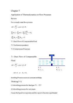
Chapter 7 Application of Thermodynamics to Flow Processes Review For a steady-state flow process M+答+g=0+形 名-2a8-2增a (∑B)n=(∑B)+D 7.1 Duct Flow of Compressible Fluid 7.2 Turbines(expanders) 7.3 Compression Processes 7.1 Duct Flow of Compressible Fluid 2+84=Q+m H145 H3u,2, △H=0orH2=H hrottling Processoccurs at constant enthalpy Thinking(7-1) (1)throttlingprocess for idealgas T1 T2? (2)throttling process for wet steam Cause the liquid to evaporateand the vaporto become superheated
Chapter 7 Application of Thermodynamics to Flow Processes Review For a steady-state flow process 2 2 s u H g z Q W + + = + , j j j i i G j i j j Q m S m S S T − − = ( ) ( ) B B D in out = + 7.1 Duct Flow of Compressible Fluid 7.2 Turbines (expanders) 7.3 Compression Processes 7.1 Duct Flow of Compressible Fluid 2 2 u H g z Q W + + = + hrottling Process occurs at constant enthalpy Thinking(7-1) (1) throttling process for ideal gas T1、T2? (2) throttling process for wet steam Cause the liquid to evaporate and the vapor to become superheated 2 1 = = H or H H 0 1 1 1 1 1 P T H u z 2 2 2 2 2 P T H u z

(3)throttlingprocess for saturatedliquid Some ofliquid vaporizes or flashes 7.1.1 Throttling Process Joule-Thomsoncoefficient - 微分节流效应系数,有时用山,表示 节流过程中压力变化所引起的温度变化: A=T,-I=∫udP Joule-Thomson coefficient ())()- (》=c ,- 别 部-().(〔) ,-r- V=ZRT/P
(3) throttling process for saturated liquid Some of liquid vaporizes or flashes 7.1.1 Throttling Process Joule-Thomson coefficient H s T P = 微分节流效应系数,有时用 J 表示 节流过程中压力变化所引起的温度变化: 2 1 2 1 d P H P = − = T T T P Joule-Thomson coefficient 1 y x F F x y x y F = − P P H C T = T P H V V T P T = − H T P = H P T T T H P H P = − 1 P T H H T P − = − T P H V V T P T = − V ZRT P = /
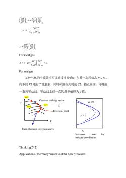
),-( “=部) u For ideal gas 21-0 For real gas 某种气体的节流效应可以通过实验确定在某一高压状态P1,T1, 向不同P2进行节流膨胀,同时可测得此时的2,描点画图,可得出 一系列等焓线。等焓线上任一点的斜率值即为μ值。 H0 Constant enthalpy curve 0 Joule-Thomson inversion curve P Inversion curves for reduced coordinates Thinking(7-2) Application ofthermodynamics to other flow processes
2 T P H Z RT P P T = − 1 P T H C P = − 2 P P RT Z C P T = For ideal gas 2 1 0 P P RT Z Z C P T = = = For real gas 某种气体的节流效应可以通过实验确定.在某一高压状态 P1,T1, 向不同 P2 进行节流膨胀,同时可测得此时的 T2,描点画图,可得出 一系列等焓线。等焓线上任一点的斜率值即为 μ 值。 Thinking(7-2) Application of thermodynamics to other flow processes = 0 Joule-Thomson inversion curve 0 0 P T Constant enthalpy curve Inversion point Inversion curves for reduced coordinates Pr Tr 0 0
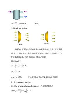
4H+4n +g△=Q+W 2 (2)Nozzle and Diffuser Diffu Nozzle 喷嘴与扩压管的结构特点是进出口截面积变化很大。流体通过 时,使压力沿着流动方向降低,而使流速加快的部件称为喷嘴。反之, 使流体流速减缓,压力升高的部件称为扩压管。 Thinking(7-2) :+g=Q+ AH+-0 2 A,-H=-蓝 流体通过焓值的改变来换取动能的调整 2 7.2 Turbines(expanders) 7.2.1 Reversible Adiabatic Expansion(可逆绝热膨胀) 容-号- d
2 2 s u H g z Q W + + = + = H Q (2) Nozzle and Diffuser 喷嘴与扩压管的结构特点是进出口截面积变化很大。流体通过 时,使压力沿着流动方向降低,而使流速加快的部件称为喷嘴。反之, 使流体流速减缓,压力升高的部件称为扩压管。 Thinking(7-2) 2 2 s u H g z Q W + + = + 2 0 2 u H + = 2 2 1 2 2 1 2 u u H H − − = 流体通过焓值的改变来换取动能的调整 7.2 Turbines (expanders) 7.2.1 Reversible Adiabatic Expansion(可逆绝热膨胀) , ( ) ( ) CV j fs G j j d mS Q mS S dt T + − = Nozzle Diffuser
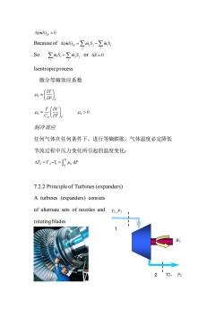
△(mS)6=0 Because of△(mS)s=∑m,S,-∑m,S S0∑ms=∑m5,orAS=0 Isentropicprocess 微分等熵效应系数 4-( %) 4>0 制冷效应 任何气体在任何条件下,进行等熵膨胀,气体温度必定降低 节流过程中压力变化所引起的温度变化: △T=T2-T=∫4dP 7.2.2 Principle of Turbines(expanders) A turbines (expanders)consists of alternate sets of nozzles and T,P rotating blades 2 T2,P2
( ) 0 = mS fs Because of ( )fs j j i i j i = − mS m S m S So i i j j i j m S m S = or = S 0 Isentropic process 微分等熵效应系数 S S T P = S P P T V C T = 0 S 制冷效应 任何气体在任何条件下,进行等熵膨胀,气体温度必定降低 节流过程中压力变化所引起的温度变化: 2 1 2 1 d P S S P = − = T T T P 7.2.2 Principle of Turbines (expanders) A turbines (expanders) consists of alternate sets of nozzles and rotating blades 1 2 T2, P2 T1, P1 Ws
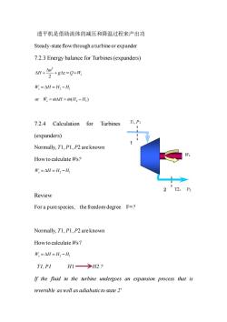
透平机是借助流体的减压和降温过程来产出功 Steady-state flow through a turbine or expander 7.2.3 Energy balance for Turbines(expanders) 兰+g=Q+ W=△H=H2-H, or市=m△H=iH2-H) 7.2.4 Calculation for Turbines (expanders) Normally,T1,P1,P2 are known How to calculate Ws? W,=△H=H2-H Review For a purespecies,the freedom degree F=? Normally,T1,P1,P2 are known How to calculate Ws? W=△H=H2-H Tl.PI H1→H2? If the fluid in the trbine undergoes an expansion process that is reversible as well as adiabaticto state 2
透平机是借助流体的减压和降温过程来产出功 Steady-state flow through a turbine or expander 7.2.3 Energy balance for Turbines (expanders) 2 2 s u H g z Q W + + = + W H H H s = = −2 1 2 1 or ( ) W m H m H H s = = − 7.2.4 Calculation for Turbines (expanders) Normally, T1, P1, P2 are known How to calculate Ws? W H H H s = = −2 1 Review For a pure species, the freedom degree F=? Normally, T1, P1, P2 are known How to calculate Ws? W H H H s = = −2 1 T1, P1 H1 H2 ? If the fluid in the turbine undergoes an expansion process that is reversible as well as adiabatic to state 2′ 1 2 T2, P2 T1, P1 Ws
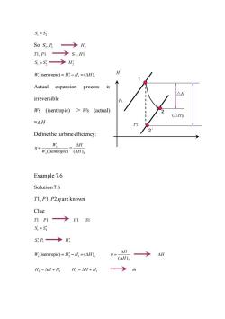
S=S: S0S,B→Hg T1,P1→S1,H1 S=Sg→H W.(isentropic)=HH=(AH), H Actual expansion process irreversible Ws (isentropic)>Ws (actual) (△H =△H Define the turbine efficiency W. AH (isentropie)(A)s Example 7.6 Solution7.6 TI,P1,P2,n are known Clue: nP1→HS1 S,=S3 SB→H: W.(isentropic)=HH=(AH), H→ (AH)s AH H,=AH+HH =AH+H →m
1 2 S S = So S , 2 2 P H2 T1, P1 S1, H1 1 2 S S = H2 s 2 1 (isentropic) ( ) W H H H s = − = Actual expansion process is irreversible Ws (isentropic) > Ws (actual) =△H Define the turbine efficiency: ( ) ( ) s s S W H W isentropic H = Example 7.6 Solution 7.6 T1, P1, P2,η are known Clue: T1 P1 H1 S1 1 2 S S = 2 2 S P H2 s 2 1 (isentropic) ( ) W H H H s = − = ( )S H H = H H H H 2 1 = + H H H 2 1 = + m P2 P1 H 1 2′ △H 2 (△H)s
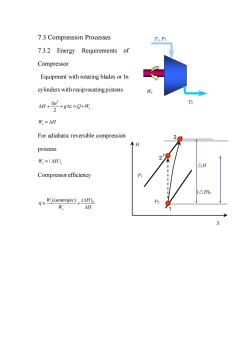
7.3 Compression Processes 7.3.2 Energy Requirements of Compressor Equipment with rotating blades or In cylinders with reciprocating pistons W,=△H For adiabatic reversible compression 个H process W,=(△H) △H P (△Hs .(isentropie)(H) △H
7.3 Compression Processes 7.3.2 Energy Requirements of Compressor Equipment with rotating blades or In cylinders with reciprocating pistons 2 2 s u H g z Q W + + = + W H s = For adiabatic reversible compression process W H s s = ( ) Compressor efficiency ( ) ( ) s S s W isentropic H W H = P2 P1 H S 1 2′ △H 2 (△H)s T2 T1, P1 Ws
按次数下载不扣除下载券;
注册用户24小时内重复下载只扣除一次;
顺序:VIP每日次数-->可用次数-->下载券;
- 《化工热力学》课程授课教案(讲义)Chapter 6 Thermodynamic properties of fluids.doc
- 《化工热力学》课程授课教案(讲义)Chapter 5 The Second Law of Thermodynamics.doc
- 《化工热力学》课程授课教案(讲义)Chapter 3 Volumetric Properties of Pure Fluids.doc
- 《化工热力学》课程授课教案(讲义)Chapter 2 The First Law and Other Basic Concepts.doc
- 《化工热力学》课程教学大纲 Thermodynamics of chemical engineering(新疆大学:黄雪莉).doc
- 海南大学:《精细化学品与工艺学》课程授课教案(讲义,共十章,负责人:刘钟馨、韩秀萍).docx
- 海南大学:《精细化学品与工艺学》课程教学课件(PPT讲稿)食品添加剂 Food additives.ppt
- 海南大学:《精细化学品与工艺学》课程教学课件(PPT讲稿)涂料(醇酸树脂涂料、丙烯酸树脂涂料).pptx
- 海南大学:《精细化学品与工艺学》课程教学课件(PPT讲稿)表面活性剂 surfactants.ppt
- 海南大学:《精细化学品与工艺学》课程教学课件(PPT讲稿)合成材料助剂.ppt
- 海南大学:《精细化学品与工艺学》课程教学课件(PPT讲稿)胶黏剂.ppt
- 海南大学:《精细化学品与工艺学》课程教学课件(PPT讲稿)绪论.ppt
- 海南大学:《精细化学品与工艺学》课程教学课件(PPT讲稿)涂料(环氧树脂涂料、聚氨酯树脂涂料).pptx
- 海南大学:《精细化学品与工艺学》课程教学课件(PPT讲稿)涂料(涂料的概念、作用和组成).pptx
- 海南大学:《精细化学品与工艺学》课程教学课件(PPT讲稿)涂料分类(涂料的分类和命名、溶剂型涂料、水性涂料).pptx
- 海南大学:《精细化学品与工艺学》课程教学课件(PPT讲稿)有机染料和颜料.pptx
- 海南大学:《精细化学品与工艺学》课程教学课件(PPT讲稿)化妆品.ppt
- 海南大学:《精细化学品与工艺学》课程教学课件(PPT讲稿)香料.ppt
- 海南大学:《精细化学品与工艺学》课程教学资源(参考资料)冠状病毒知识梳理.pptx
- 海南大学:《精细化学品与工艺学》课程教学资源(教案讲义,授课教师:韩秀萍、刘钟馨).docx
- 《化工热力学》课程授课教案(讲义)Chapter 8 Production of Power from Heat.doc
- 《化工热力学》课程授课教案(讲义)Chapter 9 Refrigeration and Liquefaction.doc
- 《化工热力学》课程授课教案(讲义)Chapter 11 Solution thermodynamics - Theory.doc
- 《化工热力学》课程授课教案(讲义)Chapter 12 Solution Thermodynamics:Application.doc
- 《化工热力学》课程授课教案(讲义)Chapter 13 Chemical-Reaction Equilibria.doc
- 《化工热力学》课程教学资源(作业习题)第1章 绪言(无答案).doc
- 《化工热力学》课程教学资源(作业习题)第2章 流体的P-V-T关系(含答案).doc
- 《化工热力学》课程教学资源(作业习题)第4章 非均相封闭体系热力学(选择题带答案).doc
- 《化工热力学》课程教学资源(作业习题)第5章 非均相体系热力学性质计算(无答案).doc
- 《化工热力学》课程教学资源(作业习题)第8章 化学反应平衡(含答案).doc
- 《化工热力学》课程教学课件(英文讲稿)纯流体性质 Volumetric Properties of Pure Fluids.pdf
- 《化工热力学》课程教学课件(英文讲稿)流体热力学性质 Thermodynamic properties of fluids.pdf
- 《化工热力学》课程教学课件(英文讲稿)热动力 Production of Power from Heat.pdf
- 《化工热力学》课程教学课件(英文讲稿)溶液热力学原理 Solution thermodynamics:Theory.pdf
- 《化工热力学》课程教学课件(英文讲稿)热功转换及可用能.pdf
- 《化工热力学》课程教学课件(PPT讲稿)第一章 绪论 Chemical Engineering thermodynamics.ppt
- 《化工热力学》课程教学课件(PPT讲稿)第二章 流体的p-V-T关系.ppt
- 《化工热力学》课程教学课件(PPT讲稿)第五章 化工过程的能量分析.ppt
- 《化工热力学》课程教学课件(PPT讲稿)第七章 相平衡.ppt
- 《化工热力学》课程教学课件(PPT讲稿)第三章 流体的热力学性质.ppt
