《机械制造工艺学》课程教学资源(英文讲稿)Chapter 2 The design principle of jigs and fixtures
Chapter2Thedesignprincipleof jigs and fixturesabstractIn order to fulfill themachining requirement of a certain job,a relatively accurate positionof theworkpiece in a machine tool in relation to the cutting tool duringthe metal cutting movementmust be ensured.Thefollowing three conditions mustbe satisfied when fulfilling such apracticalfunction, which are(1) the accurate position ofa batch of workpieces in relation to the jigs or fixtures;(2)the accurateposition of thejigs or fixturesinrelationtothemachinetool;(3)theaccurateposition ofthe cutting tool in relation to the jigs orfixtures. In this chapter, themain attention is directedto the accurate positioning of workpieces in jigs or fixtures.Thepositioning ofworkpiecesinmachine tools isindirectly achieved through jigs or fixtures.Single screw jigs or fixtures2.1Introduction of jigs or fixtures Positioning :in order to ensure the accuracy andraise the efficiency, jigs or fixtures should be used toensure the accurate position of the workpiece inrelation to the machine tool.Clamping:Inordertoensurethepositionofthelocationunderexternal force,a clampingforcemustbeimposedontheworkpiece,"SetupThe comprehensive procedure ofpositioning andclamping+Jigs or fixtures :The technological equipment to fulfllthe procedure of set up2.1.1 Classification ofjigs or fixturesJigsorfixtures canbeclassified intotwocategoriesaccordingtotheirgeneral purpose,whichare:Themostwidelyusedjigsorfixturesingeneral-purpose jigsmechanicalmanufacture,complicated structureorfixturesJigs orfixtures-Arespeciallydesignedandmadeforonejob,orspecial purpose jigsmade of somestandard elements, has a more simple,orfixturescompact, and easytouse operational structure
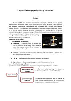
Chapter 2 The design principle of jigs and fixtures abstract In order to fulfill the machining requirement of a certain job, a relatively accurate position of the workpiece in a machine tool in relation to the cutting tool during the metal cutting movement must be ensured. The following three conditions must be satisfied when fulfilling such a practical function, which are (1)the accurate position of a batch of workpieces in relation to the jigs or fixtures; (2) the accurate position of the jigs or fixtures in relation to the machine tool;(3)the accurate position of the cutting tool in relation to the jigs or fixtures. In this chapter, the main attention is directed to the accurate positioning of workpieces in jigs or fixtures. The positioning of workpieces in machine tools is indirectly achieved through jigs or fixtures. Single screw jigs or fixtures 2.1 Introduction of jigs or fixtures v Positioning : in order to ensure the accuracy and raise the efficiency, jigs or fixtures should be used to ensure the accurate position of the workpiece in relation to the machine tool. v Clamping :In order to ensure the position of the location under external force , a clamping force must be imposed on the workpiece. v Set up :The comprehensive procedure of positioning and clamping v Jigs or fixtures :The technological equipment to fulfill the procedure of set up 2.1.1 Classification of jigs or fixtures Jigs or fixtures can be classified into two categories according to their general purpose, which are : Jigs or fixtures general-purpose jigs or fixtures special purpose jigs or fixtures ——The most widely used jigs or fixtures in mechanical manufacture ,complicated structure ——Are specially designed and made for one job, or made of some standard elements, has a more simple, compact, and easy to use operational structure
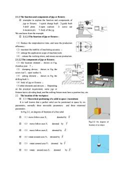
2.1.2The function and components of jigs or fixturesexamplesto explainthefunction and components ofjigs or fixtures: 1-quick change bush 2-guide bush3-drillplate2-open cushion2-screwnut6-location pin7-body ofthe jigWecanknowfromtheexample 2.1.2.1The function of jigs or fixtures:(1)Reducethenonproductivetime,and raisetheproductionefficiency;(2)maintainthestabilityofmachiningaccuracy;(3)enlarge the application scope ofmachine tools(4)release the working stress, and ensure secure production2.1.2.2 The components of jigs or fixtures:(1)the location element,shown in Fig,rhombus post7;(2)clamping deviceshown inFigthescrewnut5、openwasher4;(3) setting element , shown in Fig thedrilling bush 1 ;(4)bodyof jigs orfixtures:(5)other elements and devices,Dependingon the practical requirement, some jigs orfixtures have a dividing head, and the milling fixturemust have a positionkey,etc2.2The location of the workpiece2.2.1Theoretical positioningofa solidin space(isostatism)It is well known that a perfect solid can be positioned in space by sixand three rotationalparameters, normally three moveable parametersparametersIn Fig.2-2, six degrees of freedom of a free soliddenoted by X口(1)movefollowaxesX,Fig.2-2 Six degrees of公口denotedby(2)movefollowaxesY,freedom ofan objectdenotedbyZ口(3)movefollowaxesZ(4) rotate around axes X, denoted by X口rotate around axes Y, denoted by Y口(5)by 2口(6)denotedrotatearoundaxesZ
2.1.2 The function and components of jigs or fixtures o examples to explain the function and components of jigs or fixtures: 1-quick change bush 2-guide bush 3-drill plate 2-open cushion 2- screw nut 6-location pin 7- body of the jig We can know from the example: o 2.1.2.1The function of jigs or fixtures : (1)Reduce the nonproductive time, and raise the production efficiency; (2)maintain the stability of machining accuracy ; (3)enlarge the application scope of machine tools (4) release the working stress, and ensure secure production . 2.1.2.2 The components of jigs or fixtures: (1)the location element ,shown in Fig, rhombus post 7 ; (2) clamping device, shown in Fig the screw nut 5、open washer 4; (3) setting element , shown in Fig the drilling bush 1; (4)body of jigs or fixtures ; (5)other elements and devices ,Depending on the practical requirement, some jigs or fixtures have a dividing head, and the milling fixture must have a position key, etc. 2.2 The location of the workpiece o 2.2.1Theoretical positioning of a solid in space ( isostatism) It is well known that a perfect solid can be positioned in space by six parameters, normally three moveable parameters and three rotational parameters . In Fig.2-2, six degrees of freedom of a free solid o (1)move follow axes X, denoted by X v o (2) move follow axes Y, denoted by Y v o (3) move follow axes Z, denoted by Z v o (4)rotate around axes X, denoted by X ) o (5) rotate around axes Y, denoted by Y ) o (6) rotate around axes Z, denoted by Z ) Fig.2-2 Six degrees of freedom of an object
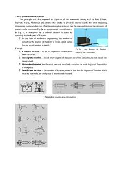
The six points location principleThis principle was first proposed by physicists of the nineteenth century such as Lord Kelven,Maxwell,Curie,Michelson and others who needed to position objects exactly for their measuringinstruments.An equivalent way ofdefining isostatism isto saythatthereactionforces on the sixpointsofcontact can be determined by the six equations of classical statics.In Fig.2-4, a workpiece has a definite location in space bycanceling its sixdegrees of freedom In the field of mechanical engineering, this method ofcanceling the degrees of freedom to locate a part, calledXthe six points location principle-Concept:Fig.2-4sixdegreesof freedomComplete location :all the sixdegrees offreedom havecancelledforaworkpiecebeen cancelledIncomplete location : not all the 6 degrees of freedom have been cancelled,but still satisfy therequirement.Redundant location:twolocation elements have both cancelled the samedegree of freedomfora workpiece. Insufficient location : the number of location points is less than the degrees of freedom whichmustbe cancelled,the workpiece is insufficiently located.(0)0LCRedundant locationand elimination
The six points location principle This principle was first proposed by physicists of the nineteenth century such as Lord Kelven, Maxwell, Curie, Michelson and others who needed to position objects exactly for their measuring instruments. An equivalent way of defining isostatism is to say that the reaction forces on the six points of contact can be determined by the six equations of classical statics. In Fig.2-4, a workpiece has a definite location in space by canceling its six degrees of freedom o In the field of mechanical engineering, this method of canceling the degrees of freedom to locate a part, called the six points location principle Concept: o Complete location :all the six degrees of freedom have been cancelled. o Incomplete location :not all the 6 degrees of freedom have been cancelled,but still satisfy the requirement. o Redundant location : two location elements have both cancelled the same degree of freedom for a workpiece. o Insufficient location :the number of location points is less than the degrees of freedom which must be cancelled, the workpiece is insufficiently located . Fig.2-4 six degrees of freedom cancelled for a workpiece Redundant location and elimination
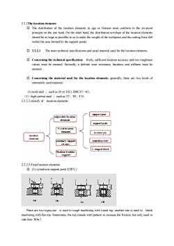
2.2.2Thelocation elementsThe distribution of the location elements in jigs or fixtures must conform to the six-pointprinciple on the one hand. On the other hand, the distribution envelope of the location elementsshould be as large as possible so as to make the weight ofthe workpiece and the cuttingforce fallwithin the area formed by the support points.2.2.2.1The main technical specifications and usual material usedfor thelocation elements. Concerning thetechnical specification:firstly,sufficient locationaccuracy and lowroughnessvalues must be ensured. Secondly, a definite wear resistance, hardness and stiffness must beensured. Concerning the material used for the location elements: generally, there are two kinds ofcommonly usedmaterial:(1)mildsteel:suchas20or20Cr,HRC55~65;(2)highcarbon steel such as T7、T8、T102.2.2.2classifyoflocationelementssupportpostadjustahlelocatinnelementssupport plateFised laaionelenentslocation pitlotafiunelementscenterdus shattAnyllarysmpportelerirn.shaped blockfloating locationsupport2.2.2.2Fixed location elements(1)cylindrical supportpost(支撑钉)taD(eThere are two types,one is used in rough machining with round top, another one is used infinishmachining with flattop.Sometimes, thetop ismade with pattern to increasethe friction, but only used inside face.Why?
2.2.2The location elements o The distribution of the location elements in jigs or fixtures must conform to the six-point principle on the one hand. On the other hand, the distribution envelope of the location elements should be as large as possible so as to make the weight of the workpiece and the cutting force fall within the area formed by the support points. o 2.2.2.1 The main technical specifications and usual material used for the location elements. o Concerning the technical specification: firstly, sufficient location accuracy and low roughness values must be ensured. Secondly, a definite wear resistance, hardness and stiffness must be ensured. o Concerning the material used for the location elements: generally, there are two kinds of commonly used material: (1) mild steel :such as 20 or 20Cr, HRC55~65; (2)high carbon steel :such as T7、T8、T10 2.2.2.2 classify of location elements 2.2.2.2 Fixed location elements o (1) cylindrical support post(支撑钉) There are two types,one is used in rough machining with round top, another one is used in finish machining with flat top. Sometimes, the top ismade with pattern to increase the friction, but only used in side face. Why?
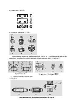
(2)Supportplate(支撑板)0(e)(3)Cylindricallocationpin(定位销)EFitting tolerance between pin and the fixture body is H7/r6 ,or H7/n6 between the bush and thefixturebody.fitting tolerancebetweenthelocationpin and thelocation bore isK7/g6orH7/f7Tapered location pinTheapplication of rhombic pin(菱形销)(4)Location centering (centering shaft,定位心轴))SDD:-2000bCThefittolerancebetweenthebore and the centerings is H7/h6 orH7/g6
(2) Support plate(支撑板) (3) Cylindrical location pin(定位销) Fitting tolerance between pin and the fixture body is H7/r6 ,or H7/n6 between the bush and the fixture body. fitting tolerance between the location pin and the location bore is K7/g6 or H7/f7. (4)Location centering (centering shaft, 定位心轴)) Tapered location pin The application of rhombic pin(菱形销) The fit tolerance between the bore and the centerings is H7/h6 or H7/g6
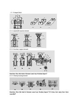
(5)V-shapedblock2.2.2.3adjustablelocationelement2.2.2.4Auxiliary supportelement(a)[b](c)Question: Does this kind ofelement cancel any freedom degree?2.2.2.5floatinglocatingelement(c)d1b)Question: Does this kind of element cancel any freedom degree? If it does, how many have beencancelled?
(5)V-shaped block 2.2.2.3 adjustable location element 2.2.2.4 Auxiliary support element Question: Does this kind of element cancel any freedom degree? 2.2.2.5 floating locating element Question: Does this kind of element cancel any freedom degree? If it does, how many have been cancelled?
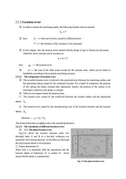
2.2.3 Location error In order to ensure the machining quality, the following formula must be ensured,4,≤There,△:thesumoferrorscausedbydifferentfactorsT-the tolerance ofthe workpiece to be machined. In this chapter, only the location errors related with the design of jigs or fixtures are discussed,Therefore, aboveformula can be rewritten as:e,+o≤Theree, ---the location error;口 ------the sum of the other errors except for the location error, which can be found inhandbooks according to the economic machining accuracy.2.2.3.1 The components of location error国The so-called location error is referred to thepositional error between themachining surface andthe operational datum caused by the workpiecelocation.Fora batch of workpieces, the positionof the cutting tool keepsconstantafter adjustment, namely,the position of the surfaceto bemachined in relationto thedatum is constant.Therearetwoaspects about thelocation error:@The location error caused by the confliction between the location datum and the operationaldatum. A,②The location error caused by the manufacturing error of the location elements and the locationdatum..AaTherefore:e,=,+dThisformula describes analgebra suminthemachiningdirection2.2.3.2The calculation of different location errors(1)TheplanelocationerrorFig.2-16shows thelocationsituationwhen twothorough holes A and B in a box-like workpiece aremachined with a boring machine. As the holes are thorough,the stop location datum is not necessary.EnsuredimensionsAlWhen hole A is machined,both the operational and thelocationdatumofdimensionAlissurfaceD,whichmeans that thedatum is superposition.Fig.2-16 the plane location error
2.2.3 Location error o In order to ensure the machining quality, the following formula must be ensured, Ds £ T o here, Ds ——the sum of errors caused by different factors. T —— the tolerance of the workpiece to be machined. o In this chapter, only the location errors related with the design of jigs or fixtures are discussed, Therefore, above formula can be rewritten as: el +w £ T here el -the location error; o w -the sum of the other errors except for the location error, which can be found in handbooks according to the economic machining accuracy. 2.2.3.1 The components of location error o The so-called location error is referred to the positional error between the machining surface and the operational datum caused by the workpiece location. For a batch of workpieces, the position of the cutting tool keeps constant after adjustment, namely, the position of the surface to be machined in relation to the datum is constant. o There are two aspects about the location error: ① The location error caused by the confliction between the location datum and the operational datum. Dn ② The location error caused by the manufacturing error of the location elements and the location datum. Dd Therefore :el = Dn+Dd This formula describes an algebra sum in the machining direction. 2.2.3.2 The calculation of different location errors o (1)The plane location error Fig.2-16 shows the location situation when two thorough holes A and B in a box-like workpiece are machined with a boring machine. As the holes are thorough, the stop location datum is not necessary. ① Ensure dimensions A1 When hole A is machined, both the operational and the location datum of dimension A1 is surface D, which means that the datum is superposition. Fig. 2-16 the plane location error
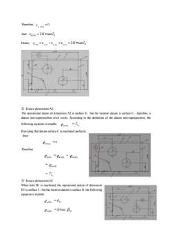
Therefore, en ca)=0And: ed(A1)=2HtanTHence,=2H·tanT=eteeeuAn)(41)ddl4A②EnsuredimensionsA2The operational datum of dimension A2 is surface E, but the location datum is surface C, therefore, adatum non-superposition error exists. Accordingtothe definition of the datum non-superposition,the=TLfollowingequationistenable:en(A2)ProvidingthatdatumsurfaceCismachinedperfectlythen=0Ea(A2)Thereforee(A2)=en(A2)+ea(A2)= En(A2)= TL③EnsuredimensionsB1When hole B1 is machined, the operational datum of dimensionBissurfaceF,butthelocationdatumissurfaceD.thefollowingequation istenable:en(BI) =OLed(BI) =2H-tan p
Therefore, 0 1 e = n(A ) And: H Tb ed (A1) = 2 · tan Hence, H Tb e e e e l n A d A d A 2 tan ( 1) ( 1) ( 1) (A1) = + = = · ② Ensure dimensions A2 The operational datum of dimension A2 is surface E,but the location datum is surface C,therefore, a datum non-superposition error exists. According to the definition of the datum non-superposition, the following equation is tenable: en(A2) = L2 T Providing that datum surface C is machined perfectly, then ed (A2) =0 Therefore el(A2) =en(A2) + ed (A2) = en(A2) = L2 T ③ Ensure dimensions B1 When hole B1 is machined, the operational datum of dimension B1 is surface F,but the location datum is surface D. the following equation is tenable: en(B1) = L1 d ed (B1) =2H·tan d b
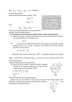
hence,ei(BI)=o,+2h·tang=en(BI) ++ ed(B)EnsuredimensionsB2dimensions B2thelocationdatum is surfaceC,then:en(m2) =0=0ed(B2)hence,= 0ei(B2)= e n(B2) +ed(B2)In most cases, the manufacturing error is not considered whenthe plane is used as the location element.(2) The location error when the internal cylindrical surface is used as the location datumWhentheworkpieceismounted inthecentering,asboththeoperational and locationdatumisthe centering,thedatum is in superposition.thene,=0口s the clearance fit is applied between the hole of the workpiece and the centering, and themanufacture error isalso involved,the position of the central line of the hole varies.Thepositional error of the datum is:e=en+ed=edTaking the diameter dimension of the hole as D+, the diameter dimension of the centering, and the minimum fit clearance as Cmmn, the situations will be considered according to theasdpositionofthecentering@when the centering is put in the vertical directionS.shown as Fig.a, the positional variation of the hole is calculatedfaccording to themaximumdimension of thehole andtheminimum dimension of the centering,which is(Ip++Cmm)e定=0,0,=2(222=T,β+T,+CmiFig a=Cmax②when the centering is put in the horizontal directionshown as Fig.(b),the workpieceis always on the same side of the centeringbecause of itsHin thedead-weight,and the positional variation of the central lineofthehole isverticaldirection.ThemaximumvalueisFigb
hence , el(B1) =en(B1) + ed (B1) =d d b L1 + 2h · tan ④ Ensure dimensions B2 dimensions B2 the location datum is surface C,then: en(B2) =0 ed (B2) =0 hence , el(B2) =en(B2) +ed (B2) = 0 In most cases, the manufacturing error is not considered when the plane is used as the location element. (2)The location error when the internal cylindrical surface is used as the location datum o When the workpiece is mounted in the centering, as both the operational and location datum is the centering, the datum is in superposition. then en =0 o s the clearance fit is applied between the hole of the workpiece and the centering, and the manufacture error is also involved, the position of the central line of the hole varies.The positional error of the datum is: el =en +ed =ed Taking the diameter dimension of the hole as D +dD ,the diameter dimension of the centering asd -dd , and the minimum fit clearance asCmin ,the situations will be considered according to the position of the centering. ①when the centering is put in the vertical direction o shown as Fig.a, the positional variation of the hole is calculated according to the maximum dimension of the hole and the minimum dimension of the centering, which is: max min min 1 2 ) 2 2 2 2( C T T C T T C e O O D d D d = = + + 定 = = + + ②when the centering is put in the horizontal direction shown as Fig. (b),the workpiece is always on the same side of the centering because of its dead-weight,and the positional variation of the central line of the hole is in the vertical direction. The maximum value is: Fig a Fig b
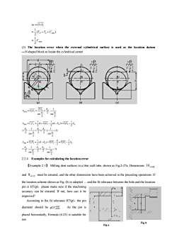
et=00-(Tp+Ta+Cmin)2(3)The location error when the external cylindrical surface is used as the location datumV-shaped block to locate the cylindrical centerr'dirr'h.8(a)(b)(c)PO,_S..1A=00,sing2AB)=CC,==d+00,-=(d-8)=00+1S8.81+1)singsng122d=(d-8,)+00Axh = D,D, =00,-8C38-%(.1-1)2m2sing222.2.4 Examples for calculating the location error[Example 2.1] Milling dent surfaces in a thin wall tube, shown as Fig.2-27a. Dimensions 10_0.08and 8_0.12 must be ensured, and the other dimensions have been achieved in the preceding operations. Ifthelocation scheme shown asFig(b)is adopted,andthefittolerancebetween thehole and the locationpin is H7/g6, please make sure if the machiningiaccuracy can be ensured. If not, how can it beimproved?AccordingtothefittoleranceH7/g6,thepindiametershouldbe$25-0.027As the pin isplaced horizontally,Formula(6.25)is suitableforuse.FigbFiga
max min 1 2 1 ( ) 2 1 C T T C e O O D d = = + + 定 = (3) The location error when the external cylindrical surface is used as the location datum —V-shaped block to locate the cylindrical center ( ) 2 sin 1 2 2 sin 2 l 1 2 a d a D = = = × d A PO O O 1) 2 sin 1 ( 2 2 2 sin 1 2 2 1 ( ) 2 1 2 1 l(B) 1 2 1 2 1 2 = × + = × + D = = + - - = + a d d a d d d d d d d O O d C C d O O d 1) 2 sin 1 ( 2 2 2 sin 1 2 2 1 2 ( ) 2 1 l(h) 1 2 1 2 1 2 = × - = × - D = = - + - = - a d d a d d d d a d d O O d d D D d O O 2.2.4 Examples for calculating the location error 【Example 2.1】 Milling dent surfaces in a thin wall tube, shown as Fig.2-27a. Dimensions 0.08 10- and 0.12 8- must be ensured, and the other dimensions have been achieved in the preceding operations. If the location scheme shown as Fig. (b) is adopted ,and the fit tolerance between the hole and the location pin is H7/g6,please make sure if the machining accuracy can be ensured. If not, how can it be improved? According to the fit tolerance H7/g6,the pin diameter should be 0.007 0.020 25- f - . As the pin is placed horizontally, Formula (6.25) is suitable for use. Fig a Fig b
按次数下载不扣除下载券;
注册用户24小时内重复下载只扣除一次;
顺序:VIP每日次数-->可用次数-->下载券;
- 《机械制造工艺学》课程教学资源(英文讲稿)Chapter 1 The Process Planning of mechanical manufacturing.pdf
- 《机械制造工艺学》课程教学资源(英文讲稿)Chapter 3 Machining Accuracy.pdf
- 《机械制造工艺学》课程授课教案(石河子大学:葛云).doc
- 《机械制造工艺学》课程考试大纲.pdf
- 《机械制造工艺学》课程教学大纲.pdf
- 《机械制造工艺学》课程教学资源(试卷习题)2 机床夹具设计原理(无答案).pdf
- 《机械制造工艺学》课程教学资源(试卷习题)1 工艺规程(无答案).pdf
- 《机械制造工艺学》课程教学资源(试卷习题)3 机械加工精度(无答案).pdf
- 《机械制造工艺学》课程教学资源(书籍文献)机械制造工艺学习题集(部分有解答).pdf
- 《机械制造工艺学》课程教学资源(试卷习题)4 机械加工质量分析与控制(无答案).pdf
- 《机械制造工艺学》课程教学资源(试卷习题)5 机器装配工艺过程设计(无答案).pdf
- 《机械制造工艺学》课程教学资源(试卷习题)6 机械制造技术的发展(无答案).pdf
- 《机械制造工艺学》课程教学资源(试卷习题)试卷3.pdf
- 《机械制造工艺学》课程教学资源(试卷习题)试卷2.pdf
- 《机械制造工艺学》课程教学资源(试卷习题)试卷1.pdf
- 《机械制造工艺学》课程教学资源(试卷习题)试卷4.pdf
- 《机械制造工艺学》课程教学资源(试卷习题)试卷7.pdf
- 《机械制造工艺学》课程教学资源(试卷习题)试卷5.pdf
- 《机械制造工艺学》课程教学资源(试卷习题)试卷6.pdf
- 《机械制造工艺学》课程教学资源(试卷习题)专业素质培养专题自测题集(无答案).pdf
- 《机械制造工艺学》课程教学资源(中文讲稿)第04章 机械加工表面质量.pdf
- 《机械制造工艺学》课程教学资源(中文讲稿)第05章 机械装配工艺.pdf
- 《机械制造工艺学》课程教学资源(中文讲稿)第03章 机械加工精度.pdf
- 《机械制造工艺学》课程教学资源(中文讲稿)第06章 机械制造技术的发展.pdf
- 《机械制造工艺学》课程教学资源(中文讲稿)第00章 基本概念(石河子大学:葛云).pdf
- 《机械制造工艺学》课程教学资源(中文讲稿)第01章 机械加工工艺规程的制订.pdf
- 《机械制造工艺学》课程教学资源(中文讲稿)第02章 机床夹具设计原理.pdf
- 《机械制造工艺学》课程教学资源(课件讲稿)Chapter 1 the process planning of mechanical manufacturing.pdf
- 《机械制造工艺学》课程教学资源(课件讲稿)Chapter 3 Machining Accuracy.pdf
- 《机械制造工艺学》课程教学资源(课件讲稿)Chapter 2 The design principle of jigs and fixtures.pdf
- 《机械制造工艺学》课程教学资源(课件讲稿)第6章 机械制造技术的发展.pdf
- 《机械制造工艺学》课程教学资源(课件讲稿)第4章 机械加工表面质量.pdf
- 《机械制造工艺学》课程教学资源(课件讲稿)第5章 机器装配工艺过程设计 Machine Assembling.pdf
- 《机械制造工艺学》课程教学资源(课件讲稿)第3章 机械加工精度.pdf
- 《机械制造工艺学》课程教学资源(课件讲稿)第2章 机床夹具设计.pdf
- 《机械制造工艺学》课程教学资源(课件讲稿)第0章 绪论 Mechanical Manufacturing Technology(石河子大学:葛云).pdf
- 《机械制造工艺学》课程教学资源(课件讲稿)第1章 机械加工工艺规程设计.pdf
- 《汽车设计》课程教学大纲 Automobile Design.pdf
- 《汽车设计》课程授课教案(文字版).docx
- 《机械制造工艺学》课程教学大纲 Technology of Machinery Manufacture.pdf
