《机械制造工艺学》课程教学资源(英文讲稿)Chapter 1 The Process Planning of mechanical manufacturing
Chapter 1TheProcessPlanningofmechanicalmanufacturingAbstractThe purpose of mechanical machining is to turn a kind of raw material into the finished parts that meetthe requirement of the product.Under given manufactureconditions, how to applyboth an economicaland efficient method, as well as a rational process routine,to achieve the desired parts is the concern ofthis chapter.Thechapterbeginswith someimportantconcepts suchasworkingprocedure,process step,cutting inone continuous feed, setup,machining position, reference datum,manufacturing process and so on1.1 Process of product1.1.1Processofproduct(生产过程)Manufacturing is the utilization and management of materials, people, equipment, and money toproduce products. For successful and economical manufacturing to be achieved, planning must start at thedesign stage and continue through the selection of materials, processes, equipment, and the scheduling ofproductionThese related processes constitute the so-called production process Process of productinvolve:Productdesign、prepare、transport of rawandprocessedmaterials、roughmanufacture、mechanicalmachining、heattreatment、assembly、deburring、test、paintingandpackingThese related processes constitutethe so-called productionprocess.Itis usually completed by thecoordinated work of different factories or workshops.1.1.2 Process of Part(工艺过程)Process of Part:The process by which the shape, dimensions and performance of raw material or rough casting arechanged directly by mechanical manufacturing into desired parts is called component manufactured partproduction, or process route.When parts areassembled intoa product, it is called the assemblyprocess.1.1.2.1 part production2001.61.6Partproduction consists of one or several operations inVsequence.Arough casting can be turned into a finished二1*DOteor semi-finished product by the operations.e(1)operations(工序)150300Whenoneoperator(oragroupofoperators)worksB590inadefiniteposition(onemachinetoolorclippingtable)toachieve thecontinuousmanufacturing of one orFig 1-1 is the engineering drawing of a shaftseveralparts simultaneously.Anoperationisthebasicelement of process procedureas well as oftheproductionschedule and of cost estimation.If the number of the parts in a batch is small, the manufacturing process can be completed through 5operations, whichare shown in table 1-1.Table1-1the process of shaft manufacturingWorkplaceOperationNoOperationnamefacing end , center drlling endsEnginelathe2Cylindrical TurningEngine lathe3Key way millingUpright milling machineCylindrical grindingGrinding machinedeburringClipping table
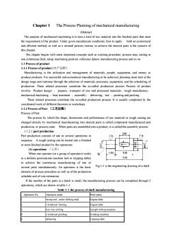
Chapter 1 The Process Planning of mechanical manufacturing Abstract The purpose of mechanical machining is to turn a kind of raw material into the finished parts that meet the requirement of the product. Under given manufacture conditions, how to apply both an economical and efficient method, as well as a rational process routine, to achieve the desired parts is the concern of this chapter. The chapter begins with some important concepts such as working procedure, process step, cutting in one continuous feed, setup, machining position, reference datum, manufacturing process and so on. 1.1 Process of product 1.1.1 Process of product (生产过程) Manufacturing is the utilization and management of materials, people, equipment, and money to produce products. For successful and economical manufacturing to be achieved, planning must start at the design stage and continue through the selection of materials, processes, equipment, and the scheduling of production. These related processes constitute the so-called production process Process of product involve:Product design 、 prepare、transport of raw and processed materials、rough manufacture、 mechanical machining 、heat treatment 、assembly、 deburring、test 、painting and packing. These related processes constitute the so-called production process. It is usually completed by the coordinated work of different factories or workshops. 1.1.2 Process of Part (工艺过程) Process of Part: The process by which the shape, dimensions and performance of raw material or rough casting are changed directly by mechanical manufacturing into desired parts is called component manufactured part production, or process route. When parts are assembled into a product, it is called the assembly process. 1.1.2.1 part production Part production consists of one or several operations in sequence. A rough casting can be turned into a finished or semi-finished product by the operations. (1) operations (工序) When one operator (or a group of operators) works in a definite position(one machine tool or clipping table) to achieve the continuous manufacturing of one or several parts simultaneously. An operation is the basic element of process procedure as well as of the production schedule and of cost estimation. If the number of the parts in a batch is small, the manufacturing process can be completed through 5 operations, which are shown in table 1-1. Table 1-1 the process of shaft manufacturing Operation No. Operation name Work place 1 facing end , center drilling ends Engine lathe 2 Cylindrical Turning Engine lathe 3 Key way milling Upright milling machine 4 Cylindrical grinding Grinding machine 6 deburring Clipping table Fig 1-1 is the engineering drawing of a shaft
For the manufacturing of the same part as Fig 1-1, if the number of parts is large, the operation 1 intable 1-1 can be divided into 2 operationsa)facing and centering one end in an engine latheby one operatorb) transferring to another engine lathe for facing and centering the another end by another operator(2)OperationStep(工步)An operationstepisthebasicelement of an operation.Oneoperationstep isdefined as anoperationthat is completed under the condition when the surface to be manufactured, the cutting parameters(includingcuttingspeed andfeed)and cuttingtool remain thesame.Whenany ofthecuttingparameters ischanged, it will become another operation step.When several surfaces of a part are manufacturedsimultaneously,it is called a composite operation step.The purpose of classifying an operation into steps is to make a complex operation more convenientand easy to analyze and describe, and to make it more efficient to organize the manufacturing and calculatethe operationtime.(3)cuttingpass(走刀)When the amount of metal to be removed is large, several cutting passes may need to be carried out.A cutting pass is a kind ofoperation step that is completed by a single type of tool to cut the samesurface under the same cutting parameters.(4)setup(安装)Before it can be machined, the part must have a proper position relative to the cutting tool, and beclamped by a fixture in the machine tool. This procedure is called the fixturing(clamping). The operationcompleted through one fixturing is called single setup.Each operation may have either single setup or several setups.In the same operation, the number of setups should be arranged to be as few as possible.If this isdone,not only can the production efficiency beraised, but also theproduction error caused by setups canbe reduced.(5)operation position(工位)In orderto reducethenumberof setups,a rotational worktableorfixture isusually used tomake sequential machiningin differentpositions possible from a single setup. The job performed in oneposition is called one operation position.Demonstration ofoperation,operation step,position and cuttingpass1.1.2.2 Impact of production type on process planningProcess planning arehighly affected by the production type.When the production type changes, the production organization and management, the layout ofworkshop and machinetools, the processmethod ofthe rawmaterial,the manufacturing equipment, suchas kinds ofcutting tool, fixture and inspection tools and the technical level ofthe operators will also variedaccordingly.Therefore,before process planning,a concise explanation of the effect of production batchsize will be given.Production type refers to the specialized classification of an enterprise in respect of a workshop,manufacturinglineorgroup,work place,and soon Generally,itcan be classified into3tys,which are,(1) Single productionThe number of workpieces with different structure or different dimensions is only one at a time, oronly in small quantity
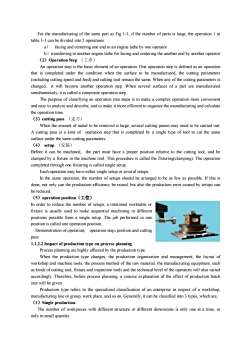
For the manufacturing of the same part as Fig 1-1, if the number of parts is large, the operation 1 in table 1-1 can be divided into 2 operations: a) facing and centering one end in an engine lathe by one operator b)transferring to another engine lathe for facing and centering the another end by another operator (2)Operation Step (工步) An operation step is the basic element of an operation. One operation step is defined as an operation that is completed under the condition when the surface to be manufactured, the cutting parameters (including cutting speed and feed) and cutting tool remain the same. When any of the cutting parameters is changed, it will become another operation step. When several surfaces of a part are manufactured simultaneously, it is called a composite operation step. The purpose of classifying an operation into steps is to make a complex operation more convenient and easy to analyze and describe, and to make it more efficient to organize the manufacturing and calculate the operation time. (3)cutting pass (走刀) When the amount of metal to be removed is large, several cutting passes may need to be carried out. A cutting pass is a kind of operation step that is completed by a single type of tool to cut the same surface under the same cutting parameters. (4) setup (安装) Before it can be machined, the part must have a proper position relative to the cutting tool, and be clamped by a fixture in the machine tool. This procedure is called the fixturing(clamping). The operation completed through one fixturing is called single setup. Each operation may have either single setup or several setups. In the same operation, the number of setups should be arranged to be as few as possible. If this is done, not only can the production efficiency be raised, but also the production error caused by setups can be reduced. (5)operation position(工位) In order to reduce the number of setups, a rotational worktable or fixture is usually used to make sequential machining in different positions possible from a single setup. The job performed in one position is called one operation position. Demonstration of operation, operation step,position and cutting pass 1.1.2.2 Impact of production type on process planning Process planning are highly affected by the production type. When the production type changes, the production organization and management, the layout of workshop and machine tools, the process method of the raw material, the manufacturing equipment, such as kinds of cutting tool, fixture and inspection tools and the technical level of the operators will also varied accordingly. Therefore, before process planning, a concise explanation of the effect of production batch size will be given. Production type refers to the specialized classification of an enterprise in respect of a workshop, manufacturing line or group, work place, and so on. Generally, it can be classified into 3 types, which are, (1)Single production The number of workpieces with different structure or different dimensions is only one at a time, or only in small quantity
For example,themanufacturing ofheavy-duty machines, specialized machines and newproducts areall done in small quantity(2)BatchproductionInoneyear,thesameproductsaremanufacturedrepeatedlyinbatchesFor example, the manufacturing of machine tools is characterized by batch production.The number ofthe same products in one batch is called the batch size. According to the batch size, it can be furtherclassified into:small batch---the characteristic is similarto that of single production;large batch--- thecharacteristic similar to large quantity production;medium batch --- the characteristic is betweenof single and large quantity production.(3) Large quantity productionThe quantity of each part being produced is large, and many work places often manufacture the sameproduct,carryingoutthesameoperationsoneachexampleoftheproductrepeatedlyFor example,themanufacturing of vehicles,trucks and bearings are all characterized by large quantityproductionThecharacteristics of differentproductiontypes are summarized inthefollowingtableTable 1-2 the main characteristics of different production typesType characteristicSingle productionBatch productionLarge quantity productionMade-to-fit,nointerchangeablefor mostinterchangeable for all parts, assembled withInterchangeabilityfinishedparts, a few repaired byselection and matching process when highinterchangeability,by fittersfittersprecise is requiredwithCastingmanuallyPartlydiecasting or dieDie casting or forgingwidelyused,and othemould,RawmaterialvoodenorforgetypeMedium accuracyhigh production methods also used.Highforging.metal removal methodfreely. Low accuracy,aneaccuracy and lowmetal removaland medium metal removalarge metal removalgeneralmachinepurposepurposemachineGeneraltoolsmixedwith highHighproduction,specialpurposeanoools.Arranged in groupsproductionandspecializedautomatic machine tools widely used. AlignedManufacturing equipmentaccordingtomachinetypmachine tools.Aligned byin flowlineand sizepart and operation typesStandardattachmentsusedwidely, few fixtures or jigHigh production fixtures or jigs widely usedigs or fixtures widely usedFixtures or jigsused. accuracy requirementaccuracy requirementmetbyfixture or setupfitting partly usedmet byfilingandfittingmethodmethodGeneral purpose cutting toolSpecial purpose cutting toolCuttingandinspectiorHigh speed cutting tool and inspectiorandinspection instrumentsand inspection instrumentaretoolsinstruments are usedarewidelyusedwidely usedHigh skillareOperation skill is required toLower operation skill requirement, and highoperatorsRequirementtooperatorsrequiredsome degreeoperation skill is required for the tool settersGeneralprocessrouteSprovided. For the key parts,Process routeDetailed process planning file is providedSimple process routing carddetailedprocessrouteICneeded
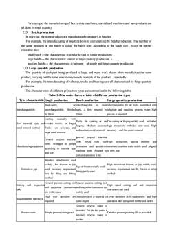
For example, the manufacturing of heavy-duty machines, specialized machines and new products are all done in small quantity (2) Batch production In one year, the same products are manufactured repeatedly in batches. For example, the manufacturing of machine tools is characterized by batch production. The number of the same products in one batch is called the batch size. According to the batch size , it can be further classified into : small batch -the characteristic is similar to that of single production; large batch - the characteristic similar to large quantity production ; medium batch - the characteristic is between of single and large quantity production. (3)Large quantity production The quantity of each part being produced is large, and many work places often manufacture the same product, carrying out the same operations on each example of the product repeatedly . For example, the manufacturing of vehicles, trucks and bearings are all characterized by large quantity production The characteristics of different production types are summarized in the following table. Table 1-2 the main characteristics of different production types Type characteristic Single production Batch production Large quantity production Interchangeability Made-to-fit, no interchangeability, finished by fitters interchangeable for most parts, a few repaired by fitters interchangeable for all parts, assembled with selection and matching process when high precise is required Raw material type and metal removal method Casting manually with wooden mould, or forged freely. Low accuracy, and large metal removal Partly die casting or die forging. Medium accuracy and medium metal removal Die casting or forging widely used,and other high production methods also used. High accuracy and low metal removal Manufacturing equipment General purpose machine tools. Arranged in groups according to machine type and size general purpose machine tools mixed with high production and specialized machine tools. Aligned by part and operation types High production, special purpose and automatic machine tools widely used. Aligned in flow line Fixtures or jigs Standard attachments used widely , few fixtures or jigs used. accuracy requirement met by filing and fitting method Jigs or fixtures widely used, fitting partly used High production fixtures or jigs widely used. accuracy requirement met by fixture or setup method Cutting and inspection tools General purpose cutting tool and inspection instruments are widely used Special purpose cutting tool and inspection instrument are widely used High speed cutting tool and inspection instruments are used Requirement to operators High skill operators are required Operation skill is required to some degree Lower operation skill requirement,and high operation skill is required for the tool setters Process route Simple process routing card General process route is provided. For the key parts, a detailed process route is needed Detailed process planning file is provided
1.2The function and design method of process planningfileThetermprocessroute(工艺规程)istheprocessplanningfileinwhichtheprocessandoperationmethod are specified.In another word, the aligned sequence of each operation, the part dimensions,tolerance and technical requirement, technical equipment and measures, cutting parameters, standardproductiontime,andlevelsofoperatorsskillareall included intheprocessplanningfile4-2-1 Theformatof process sheetIn 1982, the pre-mechanical industry ministry issued the ministry standard to regulate the format ofprocess sheet (referred to JB/Z1 187.3-82). Operation sheets vary greatly as to details:Nameofpartandtype:Name and No. of part ;Raw material ;Name ofoperation;Nameof plantBefore products are manufactured,technical and production preparation can be made beforehandaccording to the demands of process planning sheet.Accordingtotheprocessplanningsheet,thekinds,typeandnumberofmachinetools,theproductionareaneeded,theplanarrangementof equipment,thenumber,typeand classof operators requiredcan albe decided. Then, the planning of factory preparation, enlarging or rebuilding will be decided accordingly.1.2.2Thefunctionof process planning sheetThefunction of theprocess planning sheet is as follows:(1)The main technique for givingregulations to guide the production(2)Thebasisoforganizationandmanagement(3) The main information to guide the building, enlarging or rebuilding ofa mechanical factory1.2.3 Design procedures of process planning(1) Design procedures of process planningFirstly, the function, importance and working condition ofthe part should be clarified.If the design details are considered unreasonable or wrong during inspection, suggestions to modifythe design can be proposed.(2)Determination of production type according to production expectationTheexpectednumberofpartscanbecalculatedaccordingtothefollowingformula,Np=N·n(1+ a) (1+β)Where,Npthe expected number of parts in one year;N-theexpected numberofproducts inoneyear;n-thenumberofpartsinoneproduct;a -percent of spare parts;βpercent of scrap parts;tablel-6 can be used as a reference to guide the classification of production typeOutput number in oneyeartypeLightMedium sizeLarge and heavysingleBelow5Below 10Below100small5~1010~200100~500batchmedium100~300200~500500~5000300~1000500~50005000~50000arge
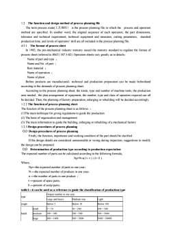
1.2 The function and design method of process planning file The term process route(工艺规程) is the process planning file in which the process and operation method are specified. In another word, the aligned sequence of each operation, the part dimensions, tolerance and technical requirement, technical equipment and measures, cutting parameters, standard production time, and levels of operators’skill are all included in the process planning file. 4·2·1 The format of process sheet In 1982, the pre-mechanical industry ministry issued the ministry standard to regulate the format of process sheet (referred to JB/Z1 187.3-82). Operation sheets vary greatly as to details: Name of part and type ; Name and No. of part ; Raw material ; Name of operation ; Name of plant . Before products are manufactured,technical and production preparation can be made beforehand according to the demands of process planning sheet. According to the process planning sheet, the kinds, type and number of machine tools, the production area needed , the plan arrangement of equipment, the number, type and class of operators required can all be decided. Then, the planning of factory preparation, enlarging or rebuilding will be decided accordingly. 1.2.2 The function of process planning sheet The function of the process planning sheet is as follows : (1)The main technique for giving regulations to guide the production (2) The basis of organization and management (3) The main information to guide the building, enlarging or rebuilding of a mechanical factory 1.2.3 Design procedures of process planning (1)Design procedures of process planning Firstly, the function, importance and working condition of the part should be clarified. If the design details are considered unreasonable or wrong during inspection, suggestions to modify the design can be proposed. (2) Determination of production type according to production expectation The expected number of parts can be calculated according to the following formula, Np=N·n(1+α) ·(1+β) Where, Np—the expected number of parts in one year; N —the expected number of products in one year; n —the number of parts in one product ; α—percent of spare parts; β—percent of scrap parts; table1—6 can be used as a reference to guide the classification of production type Output number in one year type Large and heavy Medium size Light single Below 5 Below 10 Below 100 small 5~10 10~200 100~500 batch medium 100~300 200~500 500~5000 large 300~1000 500~5000 5000~50000
Large quantityBeyond1000Beyond5000Beyond50000To classify theproduction type, both the expected number and the volume, weight of the part shouldbetaken into account(3)Determination of rawmaterial typeThe determination of raw material is related with the part geometrical shape, dimensions, mechanicalperformanceofmaterial and production type,current production conditions oftheworkshop.Casting:includes cast steel, cast iron, cast alloy etc.The shape of the casts can vary from complicationtosimplicity,anddimensionscanbeverylargeForging: has better mechanical performance than castings, however. many intricate and cored shapespossible in casting cannot be forged.Profiled bar: The shape of cross section can be round, rectangular or other different shapes. Bars areoftenmachined into shafts,dishes orround shells with engine lathe,turret lathe,orautomatic or semiautomaticlathe,and thedimensions canvaryfrom smalltomediumsize.but itsthicknessis limited withina range.Welding:for complicated and large parts canbewelded from profiled bar orforged parts,but thewelded partperformsbadlyin somerespectsEngineering plastic:used widely in mechanical manufacturing in recent years. Its shape can vary fromsimple to complicated, and the dimension accuracy is high, but mechanical performance is weak.In large batch or largequantityproduction,highlyprecise and efficientmanufacturingmethods for rawmaterial areoften used, suchasdie casting,precisecasting,dieforging,cold punching,andpowdermetallurgy.All thesemethodsmaketherawmaterial shapeclosetothatof thefinal designpart.Therefore,thelabor required in metal removal can be greatly reduced,sometimes even no metal removal is needed.Not only can the material be saved, but also the mechanical manufacturing cost can be reducedInsingle or small batch production, sand casting with wooden mould or free deformed forging areoften used. Therefore, the accuracy is low, the cost is high, the acceptance ratio is low, and the laborengaged in metal removal is large.(4)ProcessrouteplanningIt includes selection of mounting surface and machining method, classification of process phases,sequencing the operations,determining thedegreeof operation distribution,arrangementof hot working orinspection and other auxiliary operations(5)selection ofmachinetools,technical equipment (including cutting tools,fixtures and inspectiontools) and auxiliary tools for each operation.(6)selectionofmetalremoval,operationdimensionsandtolerancesforeachoperation(7)Selectionofmetal cuttingparameters and standardoperationtimes(8) technical economical analysis(9)formtheprocessfile1.3selectionofpositioningreference(datum)positioning reference is used to define the position of other points, lines or surfaces of the part arecalled thepositioning referencedatum.1.3.1ClassificationofpositioningreferencePositioningreference canbe classified into twocategories according to application purpose.1.3.1.1 Design referenceThe points, lines or surfaces that are used by designers to determine the dimensions or relativepositionsof otherpoints,lines or surfaces are calledthedesignreference.Forexample,inFigl-3a
Large quantity Beyond 1000 Beyond 5000 Beyond 50000 To classify the production type, both the expected number and the volume, weight of the part should be taken into account (3)Determination of raw material type The determination of raw material is related with the part geometrical shape, dimensions, mechanical performance of material and production type, current production conditions of the workshop. Casting:includes cast steel, cast iron, cast alloy etc. The shape of the casts can vary from complication to simplicity, and dimensions can be very large. Forging:has better mechanical performance than castings, however. many intricate and cored shapes possible in casting cannot be forged. Profiled bar:The shape of cross section can be round, rectangular or other different shapes. Bars are often machined into shafts, dishes or round shells with engine lathe, turret lathe, or automatic or semi automatic lathe, and the dimensions can vary from small to medium size. but its thickness is limited within a range. Welding:for complicated and large parts can be welded from profiled bar or forged parts,but the welded part performs badly in some respects. Engineering plastic:used widely in mechanical manufacturing in recent years. Its shape can vary from simple to complicated, and the dimension accuracy is high, but mechanical performance is weak. In large batch or large quantity production, highly precise and efficient manufacturing methods for raw material are often used, such as die casting, precise casting, die forging, cold punching ,and powder metallurgy. All these methods make the raw material shape close to that of the final design part. Therefore, the labor required in metal removal can be greatly reduced , sometimes even no metal removal is needed. Not only can the material be saved, but also the mechanical manufacturing cost can be reduced. In single or small batch production, sand casting with wooden mould or free deformed forging are often used. Therefore, the accuracy is low, the cost is high, the acceptance ratio is low, and the labor engaged in metal removal is large. (4) Process route planning It includes selection of mounting surface and machining method, classification of process phases, sequencing the operations, determining the degree of operation distribution, arrangement of hot working or inspection and other auxiliary operations . (5)selection of machine tools, technical equipment (including cutting tools, fixtures and inspection tools) and auxiliary tools for each operation. (6)selection of metal removal, operation dimensions and tolerances for each operation (7)Selection of metal cutting parameters and standard operation times 。 (8)technical economical analysis (9)form the process file 1.3 selection of positioning reference(datum) positioning reference is used to define the position of other points, lines or surfaces of the part are called the positioning reference datum. 1.3.l Classification of positioning reference Positioning reference can be classified into two categories according to application purpose. 1.3.1.1 Design reference The points, lines or surfaces that are used by designers to determine the dimensions or relative positions of other points, lines or surfaces are called the design reference. For example, in Fig1—3a
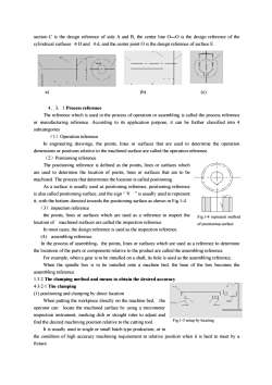
section C is the design reference of side A and B, the center line OO is the design reference of thecylindrical surfaces D and d, and the center point O is the design reference of surface E(b)a)(c)4.3.1ProcessreferenceThereferencewhichis used intheprocess of operation orassembling is calledtheprocessreferenceor manufacturing reference. According to its application purpose, it can be further classified into 4subcategories(1)OperationreferenceIn engineering drawings,the points,lines or surfaces that areused to determine the operationdimensions or positions relative to the machined surface are called the operation reference.(2)PositioningreferenceThe positioning reference is defined as the points, lines or surfaces whichareused to determinethe location of points,lines or surfacesthat are to bemachined. The process that determines the location is called positioningAsa surface isusuallyusedaspositioningreference,positioningreferenceis also called positioning surface, and the sign“V"is usually used to representit, with the bottom directed towards the positioning surface.as shown in Fig.1-4(3)inspectionreferencethe points, lines or surfaces which are used as a reference to inspect theFig.1-4 represent methodlocationof machined surfacesarecalledthe inspectionreferenceof positioning surfaceIn most cases, thedesignreference is used as the inspection reference.(4)assembling referenceIn the process of assembling,the points, lines or surfaces which are used as a reference to determinethe locations of the parts or components relativeto the product are called the assembling reference.Forexample,whenagear is tobe installed ona shaft,its hole is used as theassemblingreference,When the spindle box is to be installed onto a machine bed, the base of the box becomes theassemblingreference.1.3.2 The clamping method and means to obtain the desired accuracy4-3-2-1The clamping() positioning and clamping by direct locationWhenputtingtheworkpiecedirectly onthemachinebed,theoperatorcanlocatethemachinedsurfacebyusinga micrometerinspection instrument, marking dish or straight rules to adjust andFig.1-5 setup by locatingfind the desired machiningposition relativeto the cutting tool.It is usually used in single or small batch type production, or inthe condition of high accuracy machining requirement to relative position when it is hard to meet byafixture
section C is the design reference of side A and B, the center line O—O is the design reference of the cylindrical surfaces φD and φd, and the center point O is the design reference of surface E. 4.3.1 Process reference The reference which is used in the process of operation or assembling is called the process reference or manufacturing reference. According to its application purpose, it can be further classified into 4 subcategories (1)Operation reference In engineering drawings, the points, lines or surfaces that are used to determine the operation dimensions or positions relative to the machined surface are called the operation reference. (2)Positioning reference The positioning reference is defined as the points, lines or surfaces which are used to determine the location of points, lines or surfaces that are to be machined. The process that determines the location is called positioning. As a surface is usually used as positioning reference, positioning reference is also called positioning surface, and the sign “ V ” is usually used to represent it, with the bottom directed towards the positioning surface.as shown in Fig.1-4 (3)inspection reference the points, lines or surfaces which are used as a reference to inspect the location of machined surfaces are called the inspection reference. In most cases, the design reference is used as the inspection reference. (4) assembling reference In the process of assembling,the points, lines or surfaces which are used as a reference to determine the locations of the parts or components relative to the product are called the assembling reference. For example, when a gear is to be installed on a shaft, its hole is used as the assembling reference, When the spindle box is to be installed onto a machine bed, the base of the box becomes the assembling reference. 1.3.2 The clamping method and means to obtain the desired accuracy 4·3·2·1 The clamping (1) positioning and clamping by direct location When putting the workpiece directly on the machine bed, the operator can locate the machined surface by using a micrometer inspection instrument, marking dish or straight rules to adjust and find the desired machining position relative to the cutting tool. It is usually used in single or small batch type production, or in the condition of high accuracy machining requirement to relative position when it is hard to meet by a fixture. a) (b) (c) Fig.1-4 represent method of positioning surface Fig.1-5 setup by locating
(2)Clampingaccordingtothepre-markedtrailofoutlineThiskind ofclampingmethod is widelyused in singleor small batch typeproduction,and theerror ofthe operation itself exists, the clamping accuracy is low, usually in the range 0.2~0.5mm.Before the work is machined, the outline of the surfacetobemachined on the rawmaterial isdrawnbeforehand, then located and clamped on themachine tool according to the pre-drawn linesWhen drawing the outline to be machined, sufficient metal removal must be ensured.(3)ClampedwithafixtureThis kind of methodis convenient, fast, accurate and stable. It is widely used in batch type productionand largequantityproductionFor example, in Fig.1-1, it is an operation of machining a key in a stepped shaft.For some parts in small batches,such as the connecting rod or crank shafts,even though the batchquantity is not large, some special fixtures are still required in order to meet the specific machiningrequirement.Fig1-6 the setup of the keymachined operationObviously,the relativepositional accuracyamong different surfaces inmechanical machining,suchas parallel, the perpendicular and coaxial degrees of accuracy, can be obtained with the above clampingmethod using several clamping steps,andalso it canbeobtainedbyarranging thedifferent surfaces tobemachined inthe same clamping.Thesetwomethodsarebothcommonlyused to obtaintherelativepositional accuracy in mechanical machining.1.3.2.2Methods ofobtainingthedimensional accuracy(1)Methods to obtain the dimensional accuracy in mechanical machiningTrial cutting method :a tiny part of the surface to be machined is pre-cut, and the dimensions areinspected. Then,proper adjustment is made according to the desired requirement, and try cutting is triedagain. This process is usually repeated twice or three times to meet the final need. Finally, the wholesurface is machined according to the final adjustment@Setting dimension method :The accuracy of the machined surface is ensured by applying a cuttingtool with the required accuracy, such as a reamer, twist drill or core drill.③Adjustmethodthe accuracy is ensured by the cutting route setting device or pre-adjusted carriages to get the correctpositionofthecuttingtool inrelationwiththemachinetoolorfixture?Automaticcontrolmethodsome special automatic control devices are used to ensure the accuracy.The specific methods include1) automatic inspection- the inspection device is integrated into the machine tool. When the
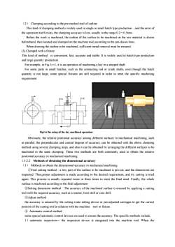
(2) Clamping according to the pre-marked trail of outline This kind of clamping method is widely used in single or small batch type production ,and the error of the operation itself exists, the clamping accuracy is low, usually in the range 0.2~0.5mm. Before the work is machined, the outline of the surface to be machined on the raw material is drawn beforehand, then located and clamped on the machine tool according to the pre-drawn lines. When drawing the outline to be machined, sufficient metal removal must be ensured. (3) Clamped with a fixture This kind of method is convenient, fast, accurate and stable. It is widely used in batch type production and large quantity production. For example, in Fig.1—1, it is an operation of machining a key in a stepped shaft. For some parts in small batches, such as the connecting rod or crank shafts, even though the batch quantity is not large, some special fixtures are still required in order to meet the specific machining requirement. Obviously, the relative positional accuracy among different surfaces in mechanical machining, such as parallel, the perpendicular and coaxial degrees of accuracy, can be obtained with the above clamping method using several clamping steps, and also it can be obtained by arranging the different surfaces to be machined in the same clamping. These two methods are both commonly used to obtain the relative positional accuracy in mechanical machining. 1.3.2.2 Methods of obtaining the dimensional accuracy (1) Methods to obtain the dimensional accuracy in mechanical machining ①Trial cutting method : a tiny part of the surface to be machined is pre-cut, and the dimensions are inspected. Then,proper adjustment is made according to the desired requirement, and try cutting is tried again. This process is usually repeated twice or three times to meet the final need. Finally, the whole surface is machined according to the final adjustment ②Setting dimension method : The accuracy of the machined surface is ensured by applying a cutting tool with the required accuracy, such as a reamer, twist drill or core drill. ③Adjust method the accuracy is ensured by the cutting route setting device or pre-adjusted carriages to get the correct position of the cutting tool in relation with the machine tool or fixture ④ Automatic control method some special automatic control devices are used to ensure the accuracy. The specific methods include, 1)automatic inspection— the inspection device is integrated into the machine tool. When the Fig1-6 the setup of the key machined operation
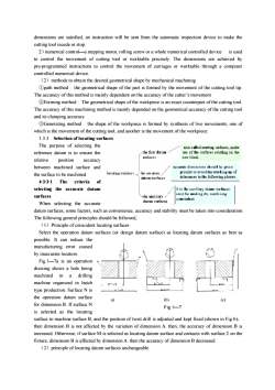
dimensions are satisfied, an instruction will be sent from the automatic inspection device to make the cutting tool recede or stop.2) numerical control—a stepping motor, rolling screw or a whole numerical controlled deviceis usedto control the movement of cutting tool or worktable precisely.The dimensions are achieved bypre-programmed instructions to control the movement of carriages or worktable through a computercontrolled numerical device.(2) methods to obtain the desired geometrical shape by mechanical machining①path method :the geometrical shape of the part is formed by the movement of the cutting tool tip.The accuracy of this method is mainlydependent on the accuracyof the cutter's movementForming method:Thegeometrical shape of the workpiece is an exact counterpart of the cutting tool.The accuracy of this machining method is mainly depended on the geometrical accuracy of the cutting tooland its clamping accuracyGenerating method :the shape of the workpiece is formed by synthesis of two movements, one ofwhich is the movement of the cutting tool, and another is the movement of the workpiece.1.3.3Selectionof locatingsurfacesThe purpose of selecting thealeo called starting ufaces, maleethe first darumuse ofthe surfaces existing on thereference datum isto ensuretherablaksurlicesrelativepositionaccuracyaceuratc dimensions shnuld hc givenbetweenmachined surface andprioriry to avoid the stacking up oflouuingwrlncesTheHEthe surface to be machined.tolerances in the following phases.rlahm gurfnoc4·3·3-1Theofcriteriaselecting the accurate datuml ix lu auxilitry dlmn aurfauexILxcdfor mnking chc machiningsurfaces-The auxiliaryconvenientdanm aurfacesWhen selecting the accuratedatum surfaces, somefactors,such as convenience,accuracyand stabilitymust betaken into considerationThefollowinggeneral principles should befollowed(1)Principle of coincident locating surfacesSelect the operation datum surfaces (or design datum surface) as locating datum surfaces as best aspossible. It can reduce themanufacturing error causedby inaccurate location.Fig.1-—7a is an operationdrawingshows a holebeingmachined in adrillingmachine organized in batchtype production Surface Nisthe operation datum surfacea)(b)(c)fordimensionB.If surfaceNFig.1—7is selected as the locatingsurface to machine surface B, and the position of twist drill is adjusted and kept fixed (shown in Fig b),then dimension B is not affected by the variation of dimension A.then, the accuracy of dimension B isincreased.Otherwise,if surfaceM is selectedas locatingdatum surfaceand contacts with surface2on thefixture,dimensionBis affectedbydimensionA.then theaccuracyofdimensionBdecreased.((2)principleoflocatingdatumsurfacesunchangeable
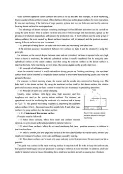
dimensions are satisfied, an instruction will be sent from the automatic inspection device to make the cutting tool recede or stop. 2)numerical control—a stepping motor, rolling screw or a whole numerical controlled device is used to control the movement of cutting tool or worktable precisely. The dimensions are achieved by pre-programmed instructions to control the movement of carriages or worktable through a computer controlled numerical device. (2)methods to obtain the desired geometrical shape by mechanical machining ①path method : the geometrical shape of the part is formed by the movement of the cutting tool tip. The accuracy of this method is mainly dependent on the accuracy of the cutter’s movement ②Forming method : The geometrical shape of the workpiece is an exact counterpart of the cutting tool. The accuracy of this machining method is mainly depended on the geometrical accuracy of the cutting tool and its clamping accuracy. ③Generating method : the shape of the workpiece is formed by synthesis of two movements, one of which is the movement of the cutting tool, and another is the movement of the workpiece. 1.3.3 Selection of locating surfaces The purpose of selecting the reference datum is to ensure the relative position accuracy between machined surface and the surface to be machined. 4·3·3·1 The criteria of selecting the accurate datum surfaces When selecting the accurate datum surfaces, some factors, such as convenience, accuracy and stability must be taken into consideration. The following general principles should be followed, (1)Principle of coincident locating surfaces Select the operation datum surfaces (or design datum surface) as locating datum surfaces as best as possible. It can reduce the manufacturing error caused by inaccurate location. Fig.1—7a is an operation drawing shows a hole being machined in a drilling machine organized in batch type production. Surface N is the operation datum surface for dimension B. If surface N is selected as the locating surface to machine surface B, and the position of twist drill is adjusted and kept fixed (shown in Fig b), then dimension B is not affected by the variation of dimension A. then, the accuracy of dimension B is increased. Otherwise, if surface M is selected as locating datum surface and contacts with surface 2 on the fixture, dimension B is affected by dimension A. then the accuracy of dimension B decreased. (2)principle of locating datum surfaces unchangeable a) (b) (c) Fig.1—7
Makedifferentoperationdatum surfacesthesameas faras possible.For example,in shaftmachiningthe two centered holes at the two ends ofthe shaft are often used as the datum surfaces for mostoperartionIn box part machining,if thebatch is of largequantity,aplaneand two pinholes are used as the commonlocatingdatumsurfaceformostoperations.The advantage of datum surfaces remaining unchanged is that different operations can be carried outusing thesamefixture.Thus it reduces thetimeand cost of fixture design and manufacture, speedsup theprocessof productionpreparation,andreducestheproductioncost.Ifmostsurfacesusethesamegroupofdatum surfaces, the error caused by datum surfaces transition will be reduced, and the position accuracyamongdifferentsurfacescanalsobeensured.(3)principleof beingdatum surfaceswith eachotherandmachiningtime after timeif the position accuracy requirement between two surfaces is high, it can be ensured by using thisprincipleFor instance, as the coaxial degree between inner and out cylindrical surfaces is required to be very highwhen a sleeve is machined,the external cylindrical surface is usually machined first by using the innercylindrical surface as the datum surface,and then using the external surfaceas the datum surface tomachinethe hole.After machining several times,the coaxial degree can begreatly improved.(4)principleofself-datumsurfacewhenthe material removal is small and uniformduringprecise orfinishingmachining,themachinedsurface itself can be selected as the precise datum surface to ensure the manufacturing quality and raise theproduct efficiency.For instance, in finish reaming a hole,the reamer and the spindle are connected in floating way.Thehole itself is the datum surface.By using the machined surface itself as thedatum surface, the relativepositionalaccuracyamongsurfaces cannotberaisedbut canbeensuredbyprecedingoperations尖餐(5)Principle of stable and simple clampingUsually, some surfaces with large area, high accuracy and lowroughness are used as the precise datum surfaces.For instance, anoperational sketchfor machining theheadstock of amachine tool is shownin Fig.1—8.The general machining sequence is, machining the assembledatum surface Afirst,then machining the spindle holeB and other innersurfacesbyusing surfaceAas thedatum surface.Fig.1-8 the accurate datum1.3-3-2Selection of first datum surfacesurfaces selected in box partPrinciplemustbefollowed:machining(1)Selectthose surfaces,which havesmall anduniform materialremoval, so as to ensure sufficient and uniform material removal(2) selectthose surfaces, which do notneed machining buthavepositionaccuracy in relationtomachined surfaces.(3) select a smooth, flat and large area surface as the first datum surface to ensure safety, security andsmall error instead of surfaces with voids and flanges caused by casting.(4)Firstdatum surfacescanbeusedonlyonceandonlyinthefirstoperation.Donot reuseit as faraspossible.The guide way surface is the main working surface in machine tool. In order to keep the uniform andfine-grained metallurgied structure produced in casting to enhance its wear-resistant.In addition, small anduniformmaterial removal makes thecuttingforce small and uniform,aswell ascausing lessvibration
Make different operation datum surfaces the same as far as possible. For example, in shaft machining, the two centered holes at the two ends of the shaft are often used as the datum surfaces for most operartion. In box part machining, if the batch is of large quantity, a plane and two pin holes are used as the common locating datum surface for most operations. The advantage of datum surfaces remaining unchanged is that different operations can be carried out using the same fixture. Thus it reduces the time and cost of fixture design and manufacture, speeds up the process of production preparation, and reduces the production cost. If most surfaces use the same group of datum surfaces, the error caused by datum surfaces transition will be reduced, and the position accuracy among different surfaces can also be ensured. (3)principle of being datum surfaces with each other and machining time after time if the position accuracy requirement between two surfaces is high, it can be ensured by using this principle For instance, as the coaxial degree between inner and out cylindrical surfaces is required to be very high when a sleeve is machined, the external cylindrical surface is usually machined first by using the inner cylindrical surface as the datum surface, and then using the external surface as the datum surface to machine the hole. After machining several times, the coaxial degree can be greatly improved. (4)principle of self-datum surface when the material removal is small and uniform during precise or finishing machining,the machined surface itself can be selected as the precise datum surface to ensure the manufacturing quality and raise the product efficiency. For instance, in finish reaming a hole, the reamer and the spindle are connected in floating way. The hole itself is the datum surface. By using the machined surface itself as the datum surface, the relative positional accuracy among surfaces can not be raised but can be ensured by preceding operations. (5)Principle of stable and simple clamping Usually, some surfaces with large area, high accuracy and low roughness are used as the precise datum surfaces. For instance, an operational sketch for machining the headstock of a machine tool is shown in Fig.1—8. The general machining sequence is, machining the assemble datum surface A first,then machining the spindle hole B and other inner surfaces by using surface A as the datum surface. 1·3·3·2 Selection of first datum surface Principle must be followed: (1)Select those surfaces, which have small and uniform material removal, so as to ensure sufficient and uniform material removal . (2)select those surfaces, which do not need machining but have position accuracy in relation to machined surfaces. (3)select a smooth, flat and large area surface as the first datum surface to ensure safety, security and small error instead of surfaces with voids and flanges caused by casting. (4)First datum surfaces can be used only once and only in the first operation. Do not reuse it as far as possible. The guide way surface is the main working surface in machine tool. In order to keep the uniform and fine-grained metallurgied structure produced in casting to enhance its wear-resistant. In addition, small and uniform material removal makes the cutting force small and uniform, as well as causing less vibration. Fig.1-8 the accurate datum surfaces selected in box part machining
In Fig.1-9a, the guide way surface is first used as the datum surface , then the guide way surface ismachined by using the bottom surface as thedatumsurfaceto ensure small and uniformmaterial removal, which is shown in Fig.1-9b.If the bottom surfacewerefirstusedasthedatum surface, which is shown in Fig.1-9c, theLerror of the bottom surfacewould befullyreflected onto the surfaceof theguideway sothatthemetal removal wouldbe less uniformFig.1-10 a)in order to ensure the uniformthickness of the flange of the pulley wheel,Fig 1-9 selection of first datum surface when machining the lath bedselect the free machining surface 1 as the firstdatum surface to machine the externalcylindrical surface.Fig.1-10 b) in orderto ensure the uniform wall thicknessof the part, the external cylindrical surface A should beselected as the first datum surfaceto borethe hole1·4Designof processplanningThe main problem involves the selection of themachining method:1-1-1Selectionoffmachiningmethodanda)(b)manufacturing equipmentFig.1-10 select non-machining surface as first1.1.1.1 Selection of machining methoddatum surface(1) The economical accuracy and surface finish fordifferentmachiningmethodstheterminologyof economical machining accuracyisdefinedastheaccuracy achieved under normal conditions including perfect machine tools, necessary technicalequipment,standard skilled operators,standard timeandproduction expenditure.NIn segment 1, when the required machining accuracy isvery high, the cost of the part will be greatly increaseduntil such a threshold when the cost rises but theaccuracy cannot be improvedfurther.In segmentII,themachiningmethodand its accuracyare adaptiveto each other,and the machining error is in工限营Ainverse proportion to the cost so astoachieve thedefiniteaccuracyIn segment Il, though the accuracy requirement is very low, the cost can not be reduced infinitely.(2)Selectionofmachiningmethodand schemeFirstly, decide the machining method and scheme according to the technical specifications of everysurface which is to be machinedTable 4.7have individuallyintroduced the usual used machining method and scheme for thebasicsurfaces(including external cylindrical surface, internal hole surface and plane surface), as well as theeconomicalaccuracyand surfacefinishfor eachmethod②Thematerialpropertiesshouldbetakenintoconsideration
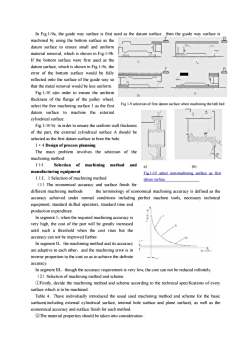
In Fig.1-9a, the guide way surface is first used as the datum surface , then the guide way surface is machined by using the bottom surface as the datum surface to ensure small and uniform material removal, which is shown in Fig.1-9b. If the bottom surface were first used as the datum surface, which is shown in Fig.1-9c, the error of the bottom surface would be fully reflected onto the surface of the guide way so that the metal removal would be less uniform. Fig.1-10 a)in order to ensure the uniform thickness of the flange of the pulley wheel, select the free machining surface 1 as the first datum surface to machine the external cylindrical surface. Fig.1-10 b) in order to ensure the uniform wall thickness of the part, the external cylindrical surface A should be selected as the first datum surface to bore the hole. 1·4 Design of process planning The main problem involves the selection of the machining method: 1·1·l Selection of machining method and manufacturing equipment 1.1.I.1 Selection of machining method (1)The economical accuracy and surface finish for different machining methods the terminology of economical machining accuracy is defined as the accuracy achieved under normal conditions including perfect machine tools, necessary technical equipment, standard skilled operators, standard time and production expenditure. In segment 1,when the required machining accuracy is very high, the cost of the part will be greatly increased until such a threshold when the cost rises but the accuracy can not be improved further. In segment II,the machining method and its accuracy are adaptive to each other,and the machining error is in inverse proportion to the cost so as to achieve the definite accuracy. In segment III,though the accuracy requirement is very low, the cost can not be reduced infinitely. (2)Selection of machining method and scheme ①Firstly, decide the machining method and scheme according to the technical specifications of every surface which is to be machined. Table 4.7have individually introduced the usual used machining method and scheme for the basic surfaces(including external cylindrical surface, internal hole surface and plane surface), as well as the economical accuracy and surface finish for each method. ②The material properties should be taken into consideration . Fig 1-9 selection of first datum surface when machining the lath bed a) (b) Fig.1-10 select non-machining surface as first datum surface
按次数下载不扣除下载券;
注册用户24小时内重复下载只扣除一次;
顺序:VIP每日次数-->可用次数-->下载券;
- 《机械制造工艺学》课程教学资源(英文讲稿)Chapter 3 Machining Accuracy.pdf
- 《机械制造工艺学》课程授课教案(石河子大学:葛云).doc
- 《机械制造工艺学》课程考试大纲.pdf
- 《机械制造工艺学》课程教学大纲.pdf
- 《机械制造工艺学》课程教学资源(试卷习题)2 机床夹具设计原理(无答案).pdf
- 《机械制造工艺学》课程教学资源(试卷习题)1 工艺规程(无答案).pdf
- 《机械制造工艺学》课程教学资源(试卷习题)3 机械加工精度(无答案).pdf
- 《机械制造工艺学》课程教学资源(书籍文献)机械制造工艺学习题集(部分有解答).pdf
- 《机械制造工艺学》课程教学资源(试卷习题)4 机械加工质量分析与控制(无答案).pdf
- 《机械制造工艺学》课程教学资源(试卷习题)5 机器装配工艺过程设计(无答案).pdf
- 《机械制造工艺学》课程教学资源(试卷习题)6 机械制造技术的发展(无答案).pdf
- 《机械制造工艺学》课程教学资源(试卷习题)试卷3.pdf
- 《机械制造工艺学》课程教学资源(试卷习题)试卷2.pdf
- 《机械制造工艺学》课程教学资源(试卷习题)试卷1.pdf
- 《机械制造工艺学》课程教学资源(试卷习题)试卷4.pdf
- 《机械制造工艺学》课程教学资源(试卷习题)试卷7.pdf
- 《机械制造工艺学》课程教学资源(试卷习题)试卷5.pdf
- 《机械制造工艺学》课程教学资源(试卷习题)试卷6.pdf
- 《机械制造工艺学》课程教学资源(试卷习题)专业素质培养专题自测题集(无答案).pdf
- 《机械制造工艺学》课程教学资源(试卷习题)试卷9.pdf
- 《机械制造工艺学》课程教学资源(英文讲稿)Chapter 2 The design principle of jigs and fixtures.pdf
- 《机械制造工艺学》课程教学资源(中文讲稿)第04章 机械加工表面质量.pdf
- 《机械制造工艺学》课程教学资源(中文讲稿)第05章 机械装配工艺.pdf
- 《机械制造工艺学》课程教学资源(中文讲稿)第03章 机械加工精度.pdf
- 《机械制造工艺学》课程教学资源(中文讲稿)第06章 机械制造技术的发展.pdf
- 《机械制造工艺学》课程教学资源(中文讲稿)第00章 基本概念(石河子大学:葛云).pdf
- 《机械制造工艺学》课程教学资源(中文讲稿)第01章 机械加工工艺规程的制订.pdf
- 《机械制造工艺学》课程教学资源(中文讲稿)第02章 机床夹具设计原理.pdf
- 《机械制造工艺学》课程教学资源(课件讲稿)Chapter 1 the process planning of mechanical manufacturing.pdf
- 《机械制造工艺学》课程教学资源(课件讲稿)Chapter 3 Machining Accuracy.pdf
- 《机械制造工艺学》课程教学资源(课件讲稿)Chapter 2 The design principle of jigs and fixtures.pdf
- 《机械制造工艺学》课程教学资源(课件讲稿)第6章 机械制造技术的发展.pdf
- 《机械制造工艺学》课程教学资源(课件讲稿)第4章 机械加工表面质量.pdf
- 《机械制造工艺学》课程教学资源(课件讲稿)第5章 机器装配工艺过程设计 Machine Assembling.pdf
- 《机械制造工艺学》课程教学资源(课件讲稿)第3章 机械加工精度.pdf
- 《机械制造工艺学》课程教学资源(课件讲稿)第2章 机床夹具设计.pdf
- 《机械制造工艺学》课程教学资源(课件讲稿)第0章 绪论 Mechanical Manufacturing Technology(石河子大学:葛云).pdf
- 《机械制造工艺学》课程教学资源(课件讲稿)第1章 机械加工工艺规程设计.pdf
- 《汽车设计》课程教学大纲 Automobile Design.pdf
- 《汽车设计》课程授课教案(文字版).docx
