《工程制图》课程PPT教学课件(双语)第4章 组合体——组合体的尺寸注法 Dimensioning Composite Solids
Dimensioning Composite Solids 组合体的尺寸标注 Basic requirements for dimensioning 标注尺寸的基本要求 Dimensioning of basic body,cutting and interpenetration bodies 基本体、截切体及相贯体的尺寸注法 Dimensioning general composite solids 组合体的尺寸注法 Exercises 练习题 请点击相应标题显示其内容 阎 返回
Dimensioning Composite Solids
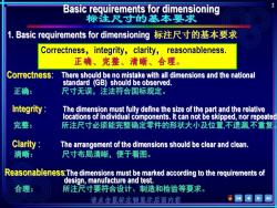
Basic requirements for dimensioning 标注尺寸的基本要求 1.Basic requirements for dimensioning标注尺寸的基本要求 Correctness,integrity,clarity,reasonableness. 正确、完整、清晰、合理。 Correctness: There should be no mistake with all dimensions and the national standard (GB)should be observed. 正确: 尺寸无误,注法符合国标规定。 Integrity The dimension must fully define the size of the part and the relative locations of individual components.It can not be skipped,nor repeated 完整: 所注尺寸必须能完整确定零件的形状大小及位置,不遗漏,不重复 Clarity The arrangement of the dimensions should be clear and clean. 清晰: 尺寸布局清晰,便于看图。 Reasonableness:The dimensions must be marked according to the requirements of design,manufacture and test. 合理: 所注尺寸要符合设计、制造和检验等要求。 请点击鼠际左键显示后面内
2

Basic requirements for dimensioning 标注尺寸的基本要求 2. Basic rules of dimensioning标注尺寸的基本规定 1)The true size of the spare part is based on the dimension marked on the drawing and has nothing to do with the size of the drawing and the accuracy of the drawings. 机件的真实大小应以图样上所注的尺寸数值为依据,与图形的大小无关。 2)There is no need to mark the unit of dimensions if it is "mm".One only needs to mark the dimensions if the units are not“mm”,such as“cm”or30 图样中尺寸以毫米为单位时不需标注计量单位的代号或名称。若采用其 他单位则必须注明相应的计量单位的代号或名称如cm(厘米)、30°度)等。 3)All dimensions marked on the drawing are dimensions of the final part.Otherwise one needs to clearly indicate on the drawing. 所标注的尺寸数字应为该图样所示机件的最后完工的尺寸否则应另加说明 4)Each dimension of the part should mark on the drawing only once.It should also be marked on a drawing that most clearly represents the corresponding constructs. 机件的每一尺寸,在图上只标注一次应标注在反映该结构最清晰的图形上 请点击鼠标左键显示后面内容
3
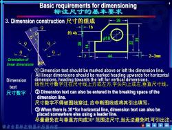
Basic requirements for dimensioning 标注尺寸的基本要求 3.Dimension construction尺寸的组成 28 -1b 约46 18 44 -2~3mm Orientation of linear dimensions 1 Dimension text should be marked above or left the dimension line. All linear dimensions should be marked heading upwards for horizontal Dimension dimensions,heading towards the left for vertical dimensions. text 线性尺寸数字注在尺寸线上方或左方,字头向上或左,垂直尺寸线。 尺寸数字 2 Dimension text can also be entered in the breaking space of the dimension line. 尺寸数字不得被图线穿过,应中断图线或将其引出填写。 3 When there is 30for horizontal line,dimension text can also be placed somewhere else using a leader line. 尽量避免在与垂直方向成30°范围注尺寸,当无法避免时,可引出注 请点击鼠标左键显示后面的察 eWP国山
4 38 3. Φ18 7 23mm 1b 约 4b 44 28 44 30 Extension line 1 24 8 9999 99 9 Dimension text Φ18 38 22 Orientation of linear dimensions
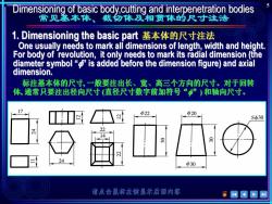
Dimensioning of basic body,cutting and interpenetration bodies 常见基本体、截勿体及相贯体的尺寸注法 1.Dimensioning the basic part基本体的尺寸注法 One usually needs to mark all dimensions of length,width and height. For body of revolution,it only needs to mark its radial dimension (the diameter symbol is added before the dimension figure)and axial dimension. 标注基本体的尺寸,一般要注出长、宽、高三个方向的尺寸。对于回转 体,通常只要注出径向尺时(直径尺寸数字前加符号“”)和轴向尺寸。 17 Φ22 中20 S30 22 4 分 24 中30 请点击鼠标左键显示后面内容
5
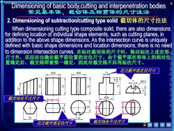
Dimensioning of basic body,cutting and interpenetration bodies 常见基本体、截勿体及相贯体的尺寸注法 2.Dimensioning of subtraction/cutting type solid截切体的尺寸注法 When dimensioning cutting type composite solid,there are also dimensions for defining location of individual shape elements,such as cutting planes,in addition to the above shape dimensions.As the intersection curve is uniquely defined with basic shape dimensions and location dimensions,there is no need to dimension intersection curves.在标注截切体的尺寸时,除应标注上述定形 尺寸外,还应注出确定藏平面位置的定位尺寸。由于截平面在形体上的相对位, 置确定后,截交线即被惟一确定,因此对截交线不应再标注尺寸。 应注截平面定位尺寸 中26 中26 3 SR13 截交线处不注尺寸 中26 面内塔 24 应注截平面定位尺寸 截交线处不注尺寸
6 截交线处不注尺寸 应注截平面定位尺寸 应注截平面定位尺寸

Dimensioning of basic body,cutting and interpenetration bodies 见基本体、截切体及相贯体的尺寸注法 3.Dimensioning of union/interpenetration type part相贯体的尺寸注法 There are also location dimensions in addition to shape dimensions for union/interpenetration type parts.With shape and location dimensions,the interpenetration curves are uniquely defined,and there is no need either to dimension interpenetration lines 因此为相贯线不应再标注尺时 请 确定, 相贯线处不注尺寸 017 φ28 φ16 中28 R8 14 9C0 S中28 27 37 点击鼠标左键显示后面内容 相贯体的定位尺付 相贯体的定位尺寸
7 R
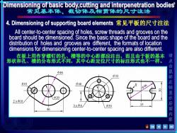
Dimensioning of basic body,cutting and interpenetration bodies 常见基本体、截切体及相贯体的尺寸注法 4.Dimensioning of supporting board elements常见平板的尺寸注法 All center-to-center spacing of holes,screw threads and grooves on the board should be dimensioned.Since the basic shape of the board and the distribution of holes and grooves are different,the formats of location dimensions for dimensioning center-to-center spacing are also different. 在板上用作穿螺钉的乳、槽等的中心距趣宫注出而具申于返的基本 形状和孔、槽的分 布形式不同,其中心距定拉尺时的标注形式也不样。 φ46 中32 击鼠标 R10 中46 b46 20 2×中10 3×φ6 Φ20 35 46 左键显示后面内 容
8

Dimensioning general composite solids 组合体的尺寸注法 1.Selection of dimension datum选定尺寸基准 ()Dimension datum尺寸基准 Dimension datum indicates common starting position of related dimensions 尺寸基准是指尺寸的起始位置,是度量尺寸的起点。 There should be at least one dimension datum for each of the three principal directions for length,width and height of the composite solid. 组合体在长、宽、高三个方向上至少都要有一个尺寸基准。 Height datum 高度基准亿) Width datum Length datum 宽度基准Y) 长度基准心) 请点击鼠标左键显示后面内
9 1. There should be at least one dimension datum for each of the three principal directions for length, width and height of the composite solid. Length datum 长度基准(X) Height datum 高度基准(Z) Width datum 宽度基准(Y) (1) Dimension datum indicates common starting position of related dimensions
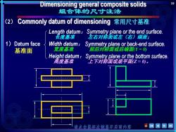
Dimensioning general composite solids 10 组合体的尺寸注法 (2) Commonly datum of dimensioning常用尺寸基准 Length datum:Symmetry plane or the end surface. 长度基准 左右对称面或左(右)端面: 1) Datum face Width datum: Symmetry plane or back-end surface. 基准面 宽度基准 前后对称面或后端面N=0 Height datum:Symmetry plane or the bottom surface. 高度基准 上下对称面或底平面Z=0)。 请点击副标左键显示后面内容
10 1)Datum face 不便于 量取。 (2) Height datum: 高度基准 上下对称面或底平面(Z = 0)。 Length datum: 长度基准 左右对称面或左(右)端面; Width datum: 宽度基准 前后对称面或后端面(Y = 0)
按次数下载不扣除下载券;
注册用户24小时内重复下载只扣除一次;
顺序:VIP每日次数-->可用次数-->下载券;
- 《工程制图》课程PPT教学课件(双语)第3章 立体投影——曲面立体的投影 Projection of Curved Solids.ppt
- 《工程制图》课程PPT教学课件(双语)第3章 立体投影——平面立体的投影 Projection of Polyhedral Solids.ppt
- 《工程制图》课程PPT教学课件(双语)第2章 平面投影——立体上直线的投影 Projection of Lines for a Solid.ppt
- 《工程制图》课程PPT教学课件(双语)第2章 平面投影——立体上点的投影 Projection of a point.ppt
- 《工程制图》课程PPT教学课件(双语)第2章 平面投影——立体上平面的投影 Projection of planes.ppt
- 《工程制图》课程PPT教学课件(双语)第2章 平面投影——正投影法原理 Principles of Orthographic Projection.ppt
- 《工程制图》课程PPT教学课件(双语)第1章 制图基本知识.ppt
- 天津大学:《工程制图》课程习题辅导(PPT课件)第9章 零件图.ppt
- 天津大学:《工程制图》课程习题辅导(PPT课件)第8章 机件基本表达方法.ppt
- 天津大学:《工程制图》课程习题辅导(PPT课件)第7章 组合体的画图和读图.ppt
- 天津大学:《工程制图》课程习题辅导(PPT课件)第6章 基本几何体相交.ppt
- 天津大学:《工程制图》课程习题辅导(PPT课件)第5章 被截切几何体的投影(2/2).ppt
- 天津大学:《工程制图》课程习题辅导(PPT课件)第5章 被截切几何体的投影(1/2).ppt
- 天津大学:《工程制图》课程习题辅导(PPT课件)第12章 轴测图.ppt
- 天津大学:《工程制图》课程习题辅导(PPT课件)第11章 装配图.ppt
- 天津大学:《工程制图》课程习题辅导(PPT课件)第10章 常用标准件和弹簧的表示法.ppt
- 天津大学:《工程制图》课程习题辅导(PPT课件)第4章 基本几何体的投影.ppt
- 天津大学:《工程制图》课程习题辅导(PPT课件)第3章 基本几何元素的投影.ppt
- 天津大学:《工程制图》课程习题辅导(PPT课件)第2章 正投影法的基本概念与基本理论(2/2).ppt
- 天津大学:《工程制图》课程习题辅导(PPT课件)第2章 正投影法的基本概念与基本理论(1/2).ppt
- 《工程制图》课程PPT教学课件(双语)第4章 组合体——组合体三视图画法 Drawing Views of Composite Solids.ppt
- 《工程制图》课程PPT教学课件(双语)第4章 组合体——组合体的形体分析 Analysis for Composite Solids.ppt
- 《工程制图》课程PPT教学课件(双语)第4章 组合体——组合体的读图 Reading Views of Composite Solids.ppt
- 大连理工大学:《画法几何及土木工程制图》课程习题解析(PPT课件)第02章 点(请使用幻灯片放映).pptx
- 大连理工大学:《画法几何及土木工程制图》课程习题解析(PPT课件)第03章 直线(请使用幻灯片放映).pptx
- 大连理工大学:《画法几何及土木工程制图》课程习题解析(PPT课件)第04章 平面(请使用幻灯片放映).pptx
- 大连理工大学:《画法几何及土木工程制图》课程习题解析(PPT课件)第05章 相对位置(请使用幻灯片放映).pptx
- 大连理工大学:《画法几何及土木工程制图》课程习题解析(PPT课件)第06章 第六章 投影变换(请使用幻灯片放映).pptx
- 大连理工大学:《画法几何及土木工程制图》课程习题解析(PPT课件)第07章 基本立体(请使用幻灯片放映).pptx
- 大连理工大学:《画法几何及土木工程制图》课程习题解析(PPT课件)第08章 截交、贯穿点(请使用幻灯片放映).pptx
- 大连理工大学:《画法几何及土木工程制图》课程习题解析(PPT课件)第09章 两立体相交(请使用幻灯片放映).pptx
- 大连理工大学:《画法几何及土木工程制图》课程习题解析(PPT课件)第10章 曲线(请使用幻灯片放映).pptx
- 大连理工大学:《画法几何及土木工程制图》课程习题解析(PPT课件)第11章 曲面(请使用幻灯片放映).pptx
- 大连理工大学:《画法几何及土木工程制图》课程习题解析(PPT课件)第12章 立体的表面展开(请使用幻灯片放映).pptx
- 大连理工大学:《画法几何及土木工程制图》课程习题解析(PPT课件)第13章 轴测投影(请使用幻灯片放映).pptx
- 大连理工大学:《画法几何及土木工程制图》课程习题解析(PPT课件)第14章 透视图(请使用幻灯片放映).pptx
- 大连理工大学:《画法几何学》课程电子教案(PPT教学课件)第一章 绪论(请使用幻灯片放映).pptx
- 大连理工大学:《画法几何学》课程电子教案(PPT教学课件)第七章 基本立体(请使用幻灯片放映).pptx
- 大连理工大学:《画法几何学》课程电子教案(PPT教学课件)第三章 直线(请使用幻灯片放映).pptx
- 大连理工大学:《画法几何学》课程电子教案(PPT教学课件)第九章 两立体相交(请使用幻灯片放映).pptx
