《电力电子技术》课程实验指导(参考资料)5SGA 30j2501

VDRM 2500V Gate turn-off Thyristor ITGQM 3000A ITSM 30 kA VTo 1.50V 5SGA30J2501 fr = 0.33m2 Vpclin 1400V Doc.No.5SYA 1213-02 Aug.2000 Patented free-floating silicon technology Low on-state and switching losses Annular gate electrode Industry standard housing Cosmic radiation withstand rating Blocking VDRM Repetitive peak off-state voltage 2500V VGR≥2V VRRM Repetitive peak reverse voltage 17V IDRM Repetitive peak off-state current ≤ 100mA VD=VDRM VGR≥2V IRRM Repetitive peak reverse current ≤ 50 mA VR=VRRM RGK=∞ Vpclink Permanent DC voltage for 100 1400V -40≤T1≤125C.Ambient cosmic FIT failure rate radiation at sea level in open air. Mechanical data (see Fig.4) Fm min. 36 kN Mounting force max. 44 kN A Acceleration: Device unclamped 50m/s2 Device clamped 200m/s2 M Weight 1.3kg Ds Surface creepage distance 2 33mm Da Air strike distance 15mm ABB Semiconductors AG reserves the right to change specifications without notice. ABB
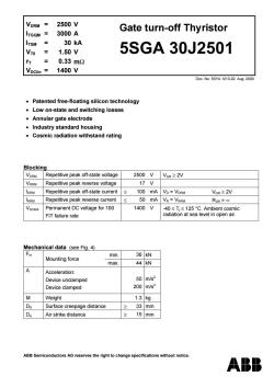
ABB Semiconductors AG reserves the right to change specifications without notice. VDRM = 2500 V ITGQM = 3000 A ITSM = 30 kA VT0 = 1.50 V rT = 0.33 mΩ VDClin = 1400 V Gate turn-off Thyristor 5SGA 30J2501 Doc. No. 5SYA 1213-02 Aug. 2000 • Patented free-floating silicon technology • Low on-state and switching losses • Annular gate electrode • Industry standard housing • Cosmic radiation withstand rating Blocking VDRM Repetitive peak off-state voltage 2500 V VGR ≥ 2V VRRM Repetitive peak reverse voltage 17 V IDRM Repetitive peak off-state current ≤ 100 mA VD = VDRM VGR ≥ 2V IRRM Repetitive peak reverse current ≤ 50 mA VR = VRRM RGK = ∞ VDClink Permanent DC voltage for 100 FIT failure rate 1400 V -40 ≤ Tj ≤ 125 °C. Ambient cosmic radiation at sea level in open air. Mechanical data (see Fig. 4) Fm min. 36 kN Mounting force max. 44 kN A Acceleration: Device unclamped Device clamped 50 200 m/s2 m/s2 M Weight 1.3 kg DS Surface creepage distance ≥ 33 mm Da Air strike distance ≥ 15 mm

5SGA30J2501 GTO Data On-state ITAVM Max.average on-state current 1300A Half sine wave,Tc=85C ITRMS Max.RMS on-state current 2040A ITSM Max.peak non-repetitive 30 kA tp= 10 ms T1=125C surge current 51 kA tp 1 ms After surge: 氏 Limiting load integral 4.50-106A2s tp 10 ms VD=VR=OV 1.30-106A2s tp= 1 ms V On-state voltage 2.50V 3000A Vro Threshold voltage 1.50V I斤=400-4000A T=125C 「T Slope resistance 0.33m2 Holding current 100A T =25C Gate VeT Gate trigger voltage 1.2V Vo =24V Ti=25C leT Gate trigger current 4.0A Ra=0.12 VGRM Repetitive peak reverse voltage 17V IGRM Repetitive peak reverse current 50 mA VGR VGRM Turn-on switching di/dtcrit Max.rate of rise of on-state 500AW/μs f=200Hz lr=3000A,T1=125C current 1000 A/us f=1Hz lGM=30 A,die/dt =20 A/us ta Delay time 2.5μs Vo 0.5 VDRM Tj =125C Rise time 5.0μs = 3000A di/dt=300Wμs ton(min) Min.on-time 100μs IGM 30A dig/dt=20A/us 飞0 Turn-on energy per pulse 2.00Ws Cs = 5uF Rs 52 Turn-off switching ITGQM Max controllable turn-off 3000A VoM VDRM dieo/dt=40AWμs current Cs=5μF Ls ≤0.3μH Storage time 25.0μs Vo =VDRM VDM VDRM Fall time 3.0μs T =125 C dico/dt=40AWμs Loff(min) Min.off-time 100μs ITGQ ITGQM Eof Turn-off energy per pulse 4.7Ws Cs 5μFRs =52 IGOM Peak turn-off gate current 1000A Ls≤0.3H ABB Semiconductors AG reserves the right to change specifications without notice. Doc.N0.5SYA1213-02Aug.2000 page 2 of 6
5SGA 30J2501 ABB Semiconductors AG reserves the right to change specifications without notice. Doc. No. 5SYA 1213-02 Aug. 2000 page 2 of 6 GTO Data On-state ITAVM Max. average on-state current 1300 A Half sine wave, TC = 85 °C ITRMS Max. RMS on-state current 2040 A ITSM 30 kA tP = 10 ms Tj Max. peak non-repetitive = 125°C surge current 51 kA tP = 1 ms After surge: I 2 t Limiting load integral 4.50⋅106 A2 s tP = 10 ms VD = VR = 0V 1.30⋅106 A2 s tP = 1 ms VT On-state voltage 2.50 V IT = 3000 A VT0 Threshold voltage 1.50 V IT = 400 - 4000 A Tj = 125 °C rT Slope resistance 0.33 mΩ IH Holding current 100 A Tj = 25 °C Gate VGT Gate trigger voltage 1.2 V VD = 24 V Tj = 25 °C IGT Gate trigger current 4.0 A RA = 0.1 Ω VGRM Repetitive peak reverse voltage 17 V IGRM Repetitive peak reverse current 50 mA VGR = VGRM Turn-on switching di/dtcrit Max. rate of rise of on-state 500 A/µs f = 200Hz IT = 3000 A, Tj = 125 °C current 1000 A/µs f = 1Hz IGM = 30 A, diG/dt = 20 A/µs td Delay time 2.5 µs VD = 0.5 VDRM Tj = 125 °C tr Rise time 5.0 µs IT = 3000 A di/dt = 300 A/µs ton(min) Min. on-time 100 µs IGM = 30 A diG/dt = 20 A/µs Eon Turn-on energy per pulse 2.00 Ws CS = 5 µF RS = 5 Ω Turn-off switching ITGQM Max controllable turn-off 3000 A VDM = VDRM diGQ/dt = 40 A/µs current CS = 5 µF LS ≤ 0.3 µH ts Storage time 25.0 µs VD = ½ VDRM VDM = VDRM tf Fall time 3.0 µs Tj = 125 °C diGQ/dt = 40 A/µs toff(min) Min. off-time 100 µs ITGQ = ITGQM Eoff Turn-off energy per pulse 4.7 Ws CS = 5 µF RS = 5 Ω IGQM Peak turn-off gate current 1000 A LS ≤ 0.3 µH

5SGA30J2501 Thermal T Storage and operating -40.125°C junction temperature range Rthuc Thermal resistance 22 K/kW Anode side cooled junction to case 27 K/kW Cathode side cooled 12 K/kW Double side cooled RthCH Thermal resistance case to 3 K/kW Single side cooled heat sink 3 K/kW Double side cooled Analytical function for transient thermal impedance: 1 2 g 4 4 Z thJC 0=∑R(1-etm) Ri(K/kW) 5.4 4.5 1.7 0.4 i=1 (s) 1.2 0.17 0.01 0.001 Zihe (K/kW) 16 14 12 10 6 0 10 5102 6101610°5106102 t(s) Fig.1 Transient thermal impedance,junction to case ABB Semiconductors AG reserves the right to change specifications without notice. D0c.N0.5SYA1213-02Aug.2000 page 3 of 6
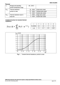
5SGA 30J2501 ABB Semiconductors AG reserves the right to change specifications without notice. Doc. No. 5SYA 1213-02 Aug. 2000 page 3 of 6 Thermal Tj Storage and operating -40.125°C junction temperature range RthJC Thermal resistance 22 K/kW Anode side cooled junction to case 27 K/kW Cathode side cooled 12 K/kW Double side cooled RthCH Thermal resistance case to 3 K/kW Single side cooled heat sink 3 K/kW Double side cooled i 12 3 4 RI (K/kW) 5.4 4.5 1.7 0.4 Analytical function for transient thermal impedance: Z (t) = R (1 - e ) 4 i 1 -t / thJC ∑ i = τi τi (s) 1.2 0.17 0.01 0.001 Fig. 1 Transient thermal impedance, junction to case

5SGA30J2501 It [A] 3000 25C 2500 25C Max 125*℃ 125C Max 2000 1500 1000 500 0.7 13 1.7 1.9 21 2.3 25 Vr[V] Fig.2 On-state characteristics ABB Semiconductors AG reserves the right to change specifications without notice. D0c.N0.5SYA1213-02Aug.2000 page 4 of 6
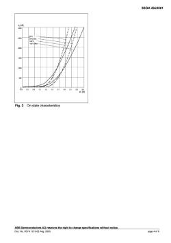
5SGA 30J2501 ABB Semiconductors AG reserves the right to change specifications without notice. Doc. No. 5SYA 1213-02 Aug. 2000 page 4 of 6 Fig. 2 On-state characteristics

5SGA30J2501 Anode di/dt TGo Vo以 0.9G0 0.9V i(t) v(t) 0.1V6 0.1G0 0.25am ftail ton ton la,Ve Gate /die/dt lGM lew 、6(t) 0.1 lGM 0.1 lGM -6(t) 0.116d VeR Qcob QeQ=QGQa+QGQb dico/dt Fig.3 General current and voltage waveforms with GTO-specific symbols 55 875 /400 。max105.8 able G. G Dimonsions in mm 5.3 Fig.4 Outline drawing.All dimensions are in millimeters and represent nominal values unless stated otherwise. ABB Semiconductors AG reserves the right to change specifications without notice. Doc.No.5SYA 1213-02 Aug.2000 page 5 of 6
5SGA 30J2501 ABB Semiconductors AG reserves the right to change specifications without notice. Doc. No. 5SYA 1213-02 Aug. 2000 page 5 of 6 Fig. 3 General current and voltage waveforms with GTO-specific symbols Fig. 4 Outline drawing. All dimensions are in millimeters and represent nominal values unless stated otherwise

5SGA30J2501 Reverse avalanche capability In operation with an antiparallel freewheeling diode,the GTO reverse voltage VR may exceed the rate value VRRM due to stray inductance and diode turn-on voltage spike at high di/dt.The GTO is then driven into reverse avalanche.This condition is not dangerous for the GTO provided avalanche time and current are below 10 us and 1000 A respectively.However,gate voltage must remain negative during this time.Recommendation VeR 10.15 V. ABB Semiconductors AG reserves the right to change specifications without notice. ABB Semiconductors AG Doc.No.5SYA 1213-02 Aug.2000 Fabrikstrasse 2 CH-5600 Lenzburg,Switzerland Tel: +41(0)628886419 Fax: +41(0)628886306 E-mail info@ch.abb.com Internet www.abbsem.com
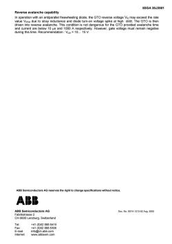
5SGA 30J2501 ABB Semiconductors AG reserves the right to change specifications without notice. ABB Semiconductors AG Doc. No. 5SYA 1213-02 Aug. 2000 Fabrikstrasse 2 CH-5600 Lenzburg, Switzerland Tel: +41 (0)62 888 6419 Fax: +41 (0)62 888 6306 E-mail info@ch.abb.com Internet www.abbsem.com Reverse avalanche capability In operation with an antiparallel freewheeling diode, the GTO reverse voltage VR may exceed the rate value VRRM due to stray inductance and diode turn-on voltage spike at high di/dt. The GTO is then driven into reverse avalanche. This condition is not dangerous for the GTO provided avalanche time and current are below 10 µs and 1000 A respectively. However, gate voltage must remain negative during this time. Recommendation : VGR = 10. 15 V
按次数下载不扣除下载券;
注册用户24小时内重复下载只扣除一次;
顺序:VIP每日次数-->可用次数-->下载券;
- 《电力电子技术》课程实验指导(参考资料)IGBT-INTRO.pdf
- 《电力电子技术》课程实验指导(参考资料)mosfet.pdf
- 石河子大学:《电力电子技术》课程教学资源(授课教案,任课教师:龚立娇).doc
- 西安邮电大学:《光纤传输技术》课程教学课件(PPT讲稿)第四章 有源器件技术.ppt
- 西安邮电大学:《光纤传输技术》课程教学课件(PPT讲稿)第五章 光纤传输线路技术.ppt
- 西安邮电大学:《光纤传输技术》课程教学课件(PPT讲稿)第六章 光纤信息传输系统.ppt
- 西安邮电大学:《光纤传输技术》课程教学课件(PPT讲稿)第一章 光纤技术.ppt
- 西安邮电大学:《光纤传输技术》课程教学课件(PPT讲稿)第三章 无源器件技术.ppt
- 西安邮电大学:《光纤传输技术》课程教学课件(PPT讲稿)绪论 Fiber-Optic Communication Technology.ppt
- 西安邮电大学:《光纤传输技术》课程教学课件(PPT讲稿)第二章 光源与光探测器.ppt
- 西安邮电大学:《光纤传输技术》课程教学实验指导书(共二十七个实验).pdf
- 西安邮电大学:《光纤传输技术》课程授课教案(共六部分).pdf
- 西安邮电大学:《光纤传输技术》课程教学大纲 Optical Fiber Transmission Technology.pdf
- 内蒙古农业大学:《单片机原理及应用》课程教学课件(讲稿)LED点阵显示实验.pdf
- 内蒙古农业大学:《单片机原理及应用》课程教学课件(讲稿)音频驱动实验.pdf
- 内蒙古农业大学:《单片机原理及应用》课程教学课件(讲稿)数字温度传感器实验.pdf
- 内蒙古农业大学:《单片机原理及应用》课程教学课件(讲稿)LCD1602显示实验.pdf
- 内蒙古农业大学:《单片机原理及应用》课程教学课件(讲稿)外部中断计数实验.pdf
- 内蒙古农业大学:《单片机原理及应用》课程教学课件(讲稿)P1口流水灯实验(风标电子).pdf
- 内蒙古农业大学:《单片机原理及应用》课程教学课件(讲稿)第十章 单片机应用系统设计方法与综合案例.pdf
- 《电力电子技术》课程实验指导(参考资料)IGBT.pdf
- 《电力电子技术》课程实验指导(参考资料)Classification.pdf
- 《电力电子技术》课程实验指导(参考资料)scr.pdf
- 《电力电子技术》课程实验指导(参考资料)MOS管——8N60.pdf
- 石河子大学:《电力电子技术》课程教学实验指导书(2014版).doc
- 《电力电子技术》课程实验指导(参考资料)BTA41-600中文资料.pdf
- 《电力电子技术》课程实验指导(参考资料)MAC97A6datasheet.pdf
- 《电力电子技术》课程实验指导(参考资料)E13005_NPN_晶体管.pdf
- 《电力电子技术》课程实验指导(参考资料)MBR3060PT中文资料.pdf
- 《电力电子技术》课程实验指导(参考资料)三相桥式整流及有源逆变电路的MATLAB仿真.pdf
- 《电力电子技术》课程实验指导(参考资料)IRFP450.pdf
- 石河子大学:《电力电子技术》课程教学课件(PPT讲稿)第5章 直流直流变流电路.ppt
- 石河子大学:《电力电子技术》课程教学课件(PPT讲稿)第7章 PWM控制技术.ppt
- 石河子大学:《电力电子技术》课程教学课件(PPT讲稿)第10章 电力电子技术的应用.ppt
- 石河子大学:《电力电子技术》课程教学课件(PPT讲稿)第5章 直流直流变流电路.ppt
- 石河子大学:《电力电子技术》课程教学课件(PPT讲稿)第8章 软开关技术.ppt
- 石河子大学:《电力电子技术》课程教学课件(PPT讲稿)第6章 交流交流变流电路.ppt
- 石河子大学:《电力电子技术》课程教学课件(PPT讲稿)第4章 逆变电路.ppt
- 石河子大学:《电力电子技术》课程教学课件(PPT讲稿)第1章 绪论(主讲:周伟绩).ppt
- 石河子大学:《电力电子技术》课程教学课件(PPT讲稿)第2章 电力电子器件.ppt
