同济大学:《传播信道特征估计和建模》课程教案讲义(射线追踪)03 Geometrical Theory of Propagation II - Diffraction, multipath
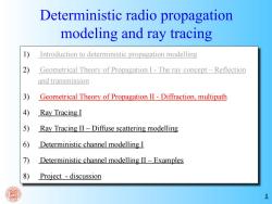
Deterministic radio propagation modeling and ray tracing Introduction to deterministic propagation modelling 2) Geometrical Theory of Propagation I-The ray concept-Reflection and transmission 3) Geometrical Theory of Propagation II-Diffraction,multipath 4) Ray Tracing I 5) Ray Tracing II-Diffuse scattering modelling 6) Deterministic channel modelling I 7) Deterministic channel modelling II-Examples 8) Project discussion
1 Deterministic radio propagation modeling and ray tracing 1) Introduction to deterministic propagation modelling 2) Geometrical Theory of Propagation I - The ray concept – Reflection and transmission 3) Geometrical Theory of Propagation II - Diffraction, multipath 4) Ray Tracing I 5) Ray Tracing II – Diffuse scattering modelling 6) Deterministic channel modelling I 7) Deterministic channel modelling II – Examples 8) Project - discussion
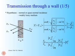
Transmission through a wall (1/5) Hypotheses:-normal or quasi-normal incidence -weakly lossy medium cos0, sin20 Pin n 1 rl-Til= Pout n 1+√e sin20, Pre 2n_ E 2n (Source:Prof.H.L.Bertoni)
Transmission through a wall (1/5) S re Sin = E re 2 2η Ein 2 2η = E re 2 Ein 2 ≈ Γ 2 pin pre pout (Source: Prof. H.L. Bertoni) * Hypotheses: - normal or quasi-normal incidence - weakly lossy medium Γ ≈ ΓTE = cosθi − n2 n1 ⎛ ⎝ ⎜ ⎞ ⎠ ⎟ 2 − sin2 θi cosθi + n2 n1 ⎛ ⎝ ⎜ ⎞ ⎠ ⎟ 2 − sin2 θi = 1− ε r 1+ ε r w
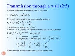
Transmission through a wall (2/5) In a lossy medium the wavenumber can be written as: k=ωVoee=0√40e0, The complex relative dielectric constant can be written as: ,=e,-je=-j0 E0E0 If the medium is weakly lossy e"<<'. A plane wave propagating through the lossy medium has the expression: E=Ege=Epe(+);with jk-@tjB Thus: 到 Where the series expansion have been truncated at first order
Transmission through a wall (2/5) k = ω µ0ε c = ω µ0ε 0ε r ε r = ε r ′ − jε r ′′ = ε ε 0 − j σ ωε 0 E = E0e− jkr = E0e −(α + jβ )r ; with jk=α+jβ k = ω µ0ε 0ε r = ω µ0ε 0 ε r ′ − jε r ′′ = ω c ε r ′ − jε r ′′ = = ω c ε r ′ 1− j ε r ′′ ε r ′ ≈ ω c ε r ′ 1− j ε r ′′ 2ε r ′ ⎛ ⎝ ⎜ ⎜ ⎞ ⎠ ⎟ ⎟ In a lossy medium the wavenumber can be written as: The complex relative dielectric constant can be written as: If the medium is weakly lossy ε ” << ε ’. A plane wave propagating through the lossy medium has the expression: Thus: Where the series expansion have been truncated at first order
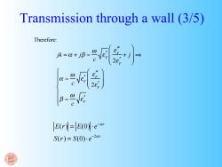
Transmission through a wall (3/5) Therefore: a-av Er=E0e“ S(r)=S(0).e-2r
Transmission through a wall (3/5) jk = α + jβ ≈ ω c ε r ′ ε r ′′ 2ε r ′ + j ⎛ ⎝ ⎜ ⎜ ⎞ ⎠ ⎟ ⎟ ⇒ α ≈ ω c ε r ′ ε r ′′ 2ε r ′ ⎛ ⎝ ⎜ ⎜ ⎞ ⎠ ⎟ ⎟ β ≈ ω c ε r ′ ⎧ ⎨ ⎪ ⎪ ⎩ ⎪ ⎪ Therefore: E(r) = E(0) ⋅ e−αr S(r) = S(0)⋅ e−2αr
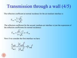
Transmission through a wall (4/5) The reflection coefficient at normal incidence for the air-medium interface is 1+Ve, The reflection coefficient for the second,medium-air interface is(see the expression of the reflection coefficients for normal incidence) Tno=ve-1 1+Ve, =-T0m Now if we consider the first interface we have 1En月
Transmission through a wall (4/5) 0 1 1 r m r ε ε − Γ = + 0 0 1 1 r m m r ε ε − Γ = = −Γ + Srefl1 Sinc1 = Erefl1 2 Ein1 2 = Γ0m 2 The reflection coefficient at normal incidence for the air-medium interface is The reflection coefficient for the second, medium-air interface is (see the expression of the reflection coefficients for normal incidence) Now if we consider the first interface we have
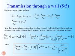
Transmission through a wall (5/5) For power conservation we have: Simel =Srem+S rasm Sinel Smel Spusm-1-Fom Sincl Now the transmitted power at the first interface,properly multiplied by the lossy-medium attenuation factor becomes the incident power at the second interface,therefore we have --f S ransm2 le=1-rP Thus: e2aw Sincl 2
Transmission through a wall (5/5) Sinc1 = Srefl1 + Strasm1 ⇒ 1= Srefl1 Sinc1 + Strasm1 Sinc1 = Γ0m 2 + Strasm1 Sinc1 Strasm1 Sinc1 = 1− Γ0m 2 Srefl2 Sinc2 = Γm0 2 = Γ0m 2 = Γ 2 ; Stransm2 Sinc2 = Stransm2 Stransm1e−2αw = Stransm2 Sinc1 1− Γ ⎛ 2 ⎝ ⎜ ⎞ ⎠ ⎟ e−2αw = 1− Γ 2 Stransm2 Sinc1 = Sout Sin = 1− Γ ⎛ 2 ⎝ ⎜ ⎞ ⎠ ⎟ 2 e−2αw ⇒ Lt = Sin Sout = e 2αw 1− Γ ⎛ 2 ⎝ ⎜ ⎞ ⎠ ⎟ 2 For power conservation we have: Now the transmitted power at the first interface, properly multiplied by the lossy-medium attenuation factor becomes the incident power at the second interface, therefore we have Thus:
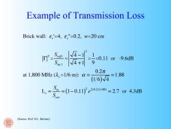
Example of Transmission Loss Brick wall:8'=4,8"=0.2,w=20 cm r1w9an 0.2π at1,800MHz(2,=1/6m):0= ==1.88 (1/6)N L,==1-0.11e20a0=27or43aB (Source:Prof.H.L.Bertoni)
Example of Transmission Loss Brick wall: ε r ' =4, ε r " =0.2, w=20 cm Γ 2 = Srefl1 Sinc1 ≈ 4 −1 4 +1 2 = 1 9 =0.11 or -9.6dB at 1,800 MHz (λo =1/6 m): α = 0.2π (1 6) 4 = 1.88 Lt = Sin Sout = (1− 0.11) 2 e 2(0.2)(1.88) = 2.7 or 4.3dB (Source: Prof. H.L. Bertoni)
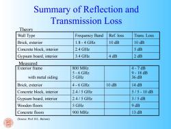
Summary of Reflection and Transmission Loss Theory Wall Type Frequency Band Ref.loss Trans.Loss Brick,exterior 1.8-4GHz 10 dB 10 dB Concrete block,interior 2.4 GHz 5 dB Gypsum board,interior 3.4 GHz 4dB 2 dB Measured Exterior frame 800 MHz 4-7dB 5-6 GHz 9-18dB with metal siding 5 GHz 36 dB Brick,exterior 4-6 GHz 10 dB 14 dB Concrete block,interior 2.4/5GHz 5/5-10dB Gypsum board,interior 2.4/5GHz 3/5dB Wooden floors 5 GHz 9 dB Concrete floors 900 MHz 13 dB (Source:Prof.H.L.Bertoni)
Summary of Reflection and Transmission Loss Wall Type Frequency Band Ref. loss Trans. Loss Brick, exterior 1.8 - 4 GHz 10 dB 10 dB Concrete block, interior 2.4 GHz 5 dB Gypsum board, interior 3.4 GHz 4 dB 2 dB Theory Measured Exterior frame with metal siding 800 MHz 5 - 6 GHz 5 GHz 4 - 7 dB 9 - 18 dB 36 dB Brick, exterior 4 - 6 GHz 10 dB 14 dB Concrete block, interior 2.4 / 5 GHz 5 / 5 - 10 dB Gypsum board, interior 2.4 / 5 GHz 3 / 5 dB Wooden floors 5 GHz 9 dB Concrete floors 900 MHz 13 dB (Source: Prof. H.L. Bertoni)
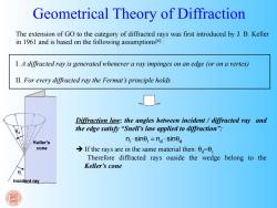
Geometrical Theory of Diffraction The extension of GO to the category of diffracted rays was first introduced by J.B.Keller in 1961 and is based on the following assumptionst61: I.A diffracted ray is generated whenever a ray impinges on an edge (or on a vertex) II.For every diffracted ray the Fermat's principle holds Diffraction law:the angles between incident diffracted ray and the edge satisfy "Snell's law applied to diffraction": Keller's nsine;=na.sined cone If the rays are in the same material then:00 Therefore diffracted rays ouside the wedge belong to the Keller's cone Incident ray
The extension of GO to the category of diffracted rays was first introduced by J. B. Keller in 1961 and is based on the following assumptions[6] : I. A diffracted ray is generated whenever a ray impinges on an edge (or on a vertex) II. For every diffracted ray the Fermat’s principle holds Incident ray Keller’s cone Diffraction law: the angles between incident / diffracted ray and the edge satisfy “Snell’s law applied to diffraction”: If the rays are in the same material then: θd=θi; Therefore diffracted rays ouside the wedge belong to the Keller’s cone ni sin i nd sinθd ⋅ θ = ⋅ Geometrical Theory of Diffraction θd θi
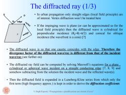
The diffracted ray (1/3) In urban propagation only straight edges (local field principle)are of interest.Vertex diffraction won't be treated here Q edge vertex If the impinging wave is plane (or can be approximated so for the local field principle)then the diffracted wave is cylindrical for wedge perpendicular incidence (-0;/2)and conical for oblique incidence (the wavefront is a cone)[7] The diffracted wave is so that one caustic coincides with the edge.Therefore the divergence factor of the diffracted wave/ray is different from that of the incident wave/ray(see further on) The diffracted ray field can be computed by solving Maxwell's equations for a plane cylindrical or spherical wave incident on a straight conducting edge [7,8,9]and somehow subtracting from the solution the incident wave and the reflected wave(s) Then the diffracted field is expanded in a Luneberg-Kline series from which only the first term (high frequency approx.)is kept in order to derive the diffraction coefficients V.Degli-Esposti,"Propagazione e pianificazione nei sistemi d'area
V. Degli-Esposti, “Propagazione e pianificazione nei sistemi d’area” • In urban propagation only straight edges (local field principle) are of interest. Vertex diffraction won’t be treated here • If the impinging wave is plane (or can be approximated so for the local field principle) then the diffracted wave is cylindrical for perpendicular incidence (θd=θi =π/2) and conical for oblique incidence (the wavefront is a cone) [7] P D QD edge The diffracted ray (1/3) • The diffracted wave is so that one caustic coincides with the edge. Therefore the divergence factor of the diffracted wave/ray is different from that of the incident wave/ray (see further on) • The diffracted ray field can be computed by solving Maxwell’s equations for a plane , cylindrical or spherical wave incident on a straight conducting edge [7, 8, 9] and somehow subtracting from the solution the incident wave and the reflected wave(s). • Then the diffracted field is expanded in a Luneberg-Kline series from which only the first term (high frequency approx.) is kept in order to derive the diffraction coefficients S
按次数下载不扣除下载券;
注册用户24小时内重复下载只扣除一次;
顺序:VIP每日次数-->可用次数-->下载券;
- 同济大学:《传播信道特征估计和建模》课程教案讲义(射线追踪)02 Geometrical Theory of Propagation I - The ray concept – Reflection and transmission.pdf
- 同济大学:《传播信道特征估计和建模》课程教案讲义(射线追踪)01 Deterministic radio propagation modeling and ray tracing - Introduction to deterministic propagation modelling.pdf
- 同济大学:《传播信道特征估计和建模》课程教学资源(课件讲稿)Chapter 3 Generic channel models.pdf
- 同济大学:《传播信道特征估计和建模》课程教学资源(课件讲稿)Chapter 2 Characterization of Propagation Channels.pdf
- 同济大学:《传播信道特征估计和建模》课程教学资源(课件讲稿)Chapter 1 Introduction - History of Channel Characterization and Modeling.pdf
- 同济大学:《传播信道特征估计和建模》课程教学资源(教案讲义)Chapter 09 Practices - channel modeling for modern communication systems.pdf
- 同济大学:《传播信道特征估计和建模》课程教学资源(教案讲义)Chapter 08 Measurement based statistical channel modeling.pdf
- 同济大学:《传播信道特征估计和建模》课程教学资源(教案讲义)Chapter 07 Statistical channel parameter estimation.pdf
- 同济大学:《传播信道特征估计和建模》课程教学资源(教案讲义)Chapter 06 Deterministic channel parameter estimation.pdf
- 同济大学:《传播信道特征估计和建模》课程教学资源(教案讲义)Chapter 05 Channel measurements.pdf
- 同济大学:《传播信道特征估计和建模》课程教学资源(教案讲义)Chapter 04 Geometry based stochastic channel modeling.pdf
- 同济大学:《传播信道特征估计和建模》课程教学资源(教案讲义)Chapter 03 Generic channel models.pdf
- 同济大学:《传播信道特征估计和建模》课程教学资源(教案讲义)Chapter 02 Characterization of Propagation Channels.pdf
- 同济大学:《传播信道特征估计和建模》课程教学资源(教案讲义)Chapter 01 Introduction.pdf
- 同济大学:《传播信道特征估计和建模》课程教学资源(教案讲义)Propagation Channel Characterization, Parameter Estimation, and Modeling for Wireless Communications - Preface.pdf
- 长沙理工大学:《现代电信交换》课程PPT教学课件(程控交换)第6章 ATM交换与B-ISDN(异步传送模式——宽带综合业务数字网).ppt
- 长沙理工大学:《现代电信交换》课程PPT教学课件(程控交换)第5章 分组交换与分组交换网.ppt
- 长沙理工大学:《现代电信交换》课程PPT教学课件(程控交换)第4章 信令系统.ppt
- 长沙理工大学:《现代电信交换》课程PPT教学课件(程控交换)第3章 电路交换与电话通信网.ppt
- 长沙理工大学:《现代电信交换》课程PPT教学课件(程控交换)第2章 交换网络.ppt
- 同济大学:《传播信道特征估计和建模》课程教案讲义(射线追踪)04 Ray Tracing I - Deterministic ray models.pdf
- 同济大学:《传播信道特征估计和建模》课程教案讲义(射线追踪)05 Ray Tracing II – Diffuse scattering modelling.pdf
- 同济大学:《传播信道特征估计和建模》课程教案讲义(射线追踪)06 Deterministic channel modelling I(static channel case).pdf
- 同济大学:《传播信道特征估计和建模》课程教案讲义(射线追踪)07 Deterministic channel modelling II – Examples.pdf
- 数字电子技术基础学习方法.doc
- 模拟电子技术学习方法.doc
- 电子技术基础学习方法探索.pdf
- 山东第一医科大学:《医学影像电子学》课程教学资源(试卷习题)医学影像电子学模式试题及参考答案(一).doc
- 山东第一医科大学:《医学影像电子学》课程教学资源(试卷习题)医学影像电子学模式试题及参考答案(二).doc
- 山东第一医科大学:《医学影像电子学》课程教学资源(试卷习题)医学影像电子学模式试题及参考答案(三).doc
- 山东第一医科大学:《医学影像电子学》课程教学资源(试卷习题)医学影像电子学模式试题及参考答案(四).doc
- 山东第一医科大学:《医学影像电子学》课程教学资源(试卷习题)医学影像电子学模式试题及参考答案(五).doc
- 山东第一医科大学:《医学影像电子学》课程教学资源(试卷习题)医学影像电子学模式试题及参考答案(六).doc
- 山东第一医科大学:《医学影像电子学》课程教学资源(试卷习题)医学影像电子学模式试题及参考答案(七).doc
- 山东第一医科大学:《医学影像电子学》课程教学资源(试卷习题)医学影像电子学模式试题及参考答案(八).doc
- 山东第一医科大学:《医学影像电子学》课程教学资源(试卷习题)医学影像电子学模式试题及参考答案(九).doc
- 山东第一医科大学:《医学影像电子学》课程教学资源(试卷习题)医学影像电子学模式试题及参考答案(十).doc
- 山东第一医科大学:《医学影像电子学》课程教学资源(试卷习题)医学影像电子学习题与答案(一)常用半导体器件.doc
- 山东第一医科大学:《医学影像电子学》课程教学资源(试卷习题)医学影像电子学习题与答案(七)信号的运算和处理.doc
- 山东第一医科大学:《医学影像电子学》课程教学资源(试卷习题)医学影像电子学习题与答案(三)多级放大电路.doc
