福州大学:《液压与气压传动》课程电子教案(PPT教学课件)Chapter 03 Hydraulic Pumps
Chapter 3 Hydraulic Pumps 妆 Chapter list 3.1 Introduction 3.2 Piston Pumps 3.3 Vane Pumps 3.4 Gear Pumps Homepage List Upwards Dowrwards Retumn Exit
Chapter 3 Hydraulic Pumps 1 Chapter list 3.1 Introduction 3.2 Piston Pumps 3.3 Vane Pumps 3.4 Gear Pumps
Chapter 3 Hydraulic Pumps 3.1 Introduction 3.1.1 Operating Principle 3.1.2 Main performance parameters in hydraulic pumps 3.1.3 Performance curves 3.1.4 Classification 3.1.5 Graphic symbols 2 Homepage List Upwards Downwards Retumn Exit
Chapter 3 Hydraulic Pumps 2 3.1 Introduction 3.1.1 Operating Principle 3.1.2 Main performance parameters in hydraulic pumps 3.1.3 Performance curves 3.1.4 Classification 3.1.5 Graphic symbols

Chapter 3 Hydraulic Pumps 3.1 Introduction Hydraulic pumps convert mechanical energy into hydraulic energy.They supply fluid to the components in the hydraulic system. 3.1.1 Operating principle 1,2-Non-return valve 3-Spring 4-Cylinder 5-Piston 6-Eccentric wheel Play y吧 Fig.3-1 Operating principle displacement pumps Homepage List Upwards Downwards Retumn Exit
Chapter 3 Hydraulic Pumps 3 3.1 Introduction 3.1.1 Operating principle Hydraulic pumps convert mechanical energy into hydraulic energy. They supply fluid to the components in the hydraulic system. 1,2-Non-return valve 3-Spring 4-Cylinder 5-Piston 6-Eccentric wheel Fig. 3-1 Operating principle displacement pumps
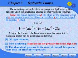
Chapter 3 Hydraulic Pumps The operating principle of every pump in a hydraulic system depends upon the alternative change of their working volumes. Note:the piston diameter as d the offset of the eccentric wheel as e,the longest stroke the piston can reach as s and the discharged oil volume V then s 2e V=(πd2/4)s=(πd2/2)e As described above,the basic conditions that constitute a hydraulic pump can be concluded as follows: (1)Oil tight chamber. (2)Flow-deploying(separate the low pressure from the high one). (3)The absolute oil pressure in the reservoir should be equal or more than the atmospheric pressure. Homepage List Upwards Downwards Retumn Exit
Chapter 3 Hydraulic Pumps 4 The operating principle of every pump in a hydraulic system depends upon the alternative change of their working volumes. Note: the piston diameter as d, the offset of the eccentric wheel as e, the longest stroke the piston can reach as s and the discharged oil volume V, then As described above, the basic conditions that constitute a hydraulic pump can be concluded as follows: (1) Oil tight chamber. (2) Flow-deploying (separate the low pressure from the high one). (3) The absolute oil pressure in the reservoir should be equal or more than the atmospheric pressure. s e = 2 2 2 V d s d e = = (π / 4) (π / 2)
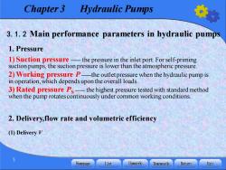
Chapter 3 Hydraulic Pumps 3.1.2 Main performance parameters in hydraulic pumps 1.Pressure 1)Suction pressure-the pressure in the inlet port.For self-priming suction pumps,the suction pressure is lower than the atmospheric pressure 2)Working pressure P-the outlet pressure when the hydraulic pump is in operation,which depends upon the overall loads. 3)Rated pressure Ps-the highest pressure tested with standard method when the pump rotates continuously under common working conditions. 2.Delivery,flow rate and volumetric efficiency (1)Delivery V Homepage List Upwards Downwards Retumn Exit
Chapter 3 Hydraulic Pumps 5 3.1.2 Main performance parameters in hydraulic pumps 1. Pressure 1) Suction pressure —— the pressure in the inlet port. For self-priming suction pumps, the suction pressure is lower than the atmospheric pressure. 2)Working pressure P ——the outlet pressure when the hydraulic pump is in operation, which depends upon the overall loads. 3) Rated pressure PS —— the highest pressure tested with standard method when the pump rotates continuously under common working conditions. 2. Delivery,flow rate and volumetric efficiency (1) Delivery V

Chapter 3 Hydraulic Pumps (2)Flowrate The flow rate consists of the average theoretical flow rate,the practical flow rate and the instantaneous theoretical flow rate. Average theoretical flow rate qt Practical flow rate g Instantaneous theoretical flow rate ash Rated flow rate 9s Homepage List Upwards Downwards Retumn Exit
Chapter 3 Hydraulic Pumps 6 (2)Flow rate The flow rate consists of the average theoretical flow rate, the practical flow rate and the instantaneous theoretical flow rate. Average theoretical flow rate qt Practical flow rate q Instantaneous theoretical flow rate qsh Rated flow rate qs
Chapter 3 Hydraulic Pumps 3. Power and efficiency (1)Input power pr (2)Output power P (3)Volumetric efficiencyv Homepage List Upwards Downwards Retumn Exit
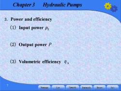
Chapter 3 Hydraulic Pumps 7 3. Power and efficiency (1) Input power pr (2) Output power P (3) Volumetric efficiency ηv

Chapter 3 Hydraulic Pumps (4)Mechanical efficiency 1m (5)Overall efficiency y and mechanical efficiency nm 4.Rotating speed (1)Rated rotating speed n:the highest rotating speed for normal continuous and long-time operation under rated pressure. (2)Highest rotating speed:the highest rotating speed for short-time operation under rated pressure,which may be higher than ns (3)Lowest speed nmin:the lowest speed of the pump for normal operation (4)Range of rotating speed:the speed range between nmin and nmax 8 Homepage List Upwards Downwards Retumn Exit
Chapter 3 Hydraulic Pumps 8 (4) Mechanical efficiencyηm (5) Overall efficiency η and mechanical efficiencyηm 4. Rotating speed (1) Rated rotating speed ns : the highest rotating speed for normal continuous and long- time operation under rated pressure. (2) Highest rotating speed nmax: the highest rotating speed for short-time operation under rated pressure, which may be higher than ns . (3) Lowest speed nmin: the lowest speed of the pump for normal operation. (4) Range of rotating speed : the speed range between nmin and nmax
Chapter 3 Hydraulic Pumps 3.1.3 Performance curves Fig.3-2 shows a performance curve of a hydraulic pump,in which the abscissa represents working pressure p of the hydraulic pump and the ordinate the volumetric efficiencyn(or the practical flow rate g),overall efficiencyn and input power P 100% n(q) Fig.3-2 Performance curves of hydraulic pumps Homepage List Upwards Downwards Retumn Exit
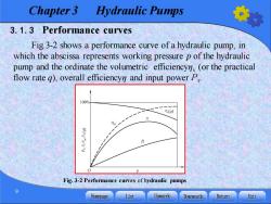
Chapter 3 Hydraulic Pumps 9 3.1.3 Performance curves Fig.3-2 shows a performance curve of a hydraulic pump, in which the abscissa represents working pressure p of the hydraulic pump and the ordinate the volumetric efficiencyηv (or the practical flow rate q), overall efficiencyη and input powerPr . Fig. 3-2 Performance curves of hydraulic pumps

Chapter 3 Hydraulic Pumps For some hydraulic pumps with certain rotating speed ranges or variable displacement capacity,the format of the general characteristic curves shown in Fig 3-3 are commonly used to reflect all their performances.The abscissa represents the working pressure p of the pump and the ordinate represents the pump's flow rate g,rotating speed n or delivery V.Fig 3-3 also shows the equal efficiency curven and the equal power curve Pri P31>2>n3 92 Flow rate q Input power P Overall efficiency n Fig.3-3 General performance curves of hydraulic pumps 10 Homepage List Upwards Downwards Retumn Exit
Chapter 3 Hydraulic Pumps 10 For some hydraulic pumps with certain rotating speed ranges or variable displacement capacity, the format of the general characteristic curves shown in Fig. 3-3 are commonly used to reflect all their performances. The abscissa represents the working pressure p of the pump and the ordinate represents the pump’s flow rate q, rotating speed n or delivery V. Fig. 3-3 also shows the equal efficiency curveηv , and the equal power curve Pri. Fig. 3-3 General performance curves of hydraulic pumps
按次数下载不扣除下载券;
注册用户24小时内重复下载只扣除一次;
顺序:VIP每日次数-->可用次数-->下载券;
- 福州大学:《液压与气压传动》课程电子教案(PPT教学课件)Chapter 02 Fundamental Hydraulic Fluid Mechanics.pptx
- 福州大学:《液压与气压传动》课程电子教案(PPT教学课件)Chapter 01 Introduction to Hydraulic and Pneumatic Transmission.pptx
- 福州大学:《液压与气压传动》课程电子教案(PPT教学课件)第12章 气动传动系统实例.pptx
- 福州大学:《液压与气压传动》课程电子教案(PPT教学课件)第11章 气动基本回路及其应用.pptx
- 福州大学:《液压与气压传动》课程电子教案(PPT教学课件)第10章 气源装置及气动元件.pptx
- 福州大学:《液压与气压传动》课程电子教案(PPT教学课件)第9章 液压系统的设计计算.pptx
- 福州大学:《液压与气压传动》课程电子教案(PPT教学课件)第8章 典型液压系统.pptx
- 福州大学:《液压与气压传动》课程电子教案(PPT教学课件)第7章 液压基本回路.pptx
- 福州大学:《液压与气压传动》课程电子教案(PPT教学课件)第6章 液压辅件.pptx
- 福州大学:《液压与气压传动》课程电子教案(PPT教学课件)第5章 液压控制阀.pptx
- 福州大学:《液压与气压传动》课程电子教案(PPT教学课件)第4章 液压马达与液压缸.pptx
- 福州大学:《液压与气压传动》课程电子教案(PPT教学课件)第3章 液压泵.pptx
- 福州大学:《液压与气压传动》课程电子教案(PPT教学课件)第2章 液压流体力学基础.pptx
- 福州大学:《液压与气压传动》课程电子教案(PPT教学课件)第1章 液压与气压传动概论.pptx
- 福州大学:《液压与气压传动》课程授课教案 Hydraulic and Pneumatic Transmission(英文讲义,负责人:陈淑梅).pdf
- 福州大学:《液压与气压传动》课程试卷及参考答案(英文).pdf
- 福州大学:《液压与气压传动》课程作业习题(英文,无答案).pdf
- 福州大学:《液压与气压传动》课程实验指导书(英汉双语)液压与气压传动实验指导书 Hydraulic and Pneumatic Transmission Instructor of Experimental Projects.pdf
- 福州大学:《液压与气压传动》课程教学大纲 Hydraulic and Pneumatic Transmission.pdf
- 福建船政交通职业学院:《物流运输与组织管理》课程教学课件(PPT讲稿)第一章 物流运输概论、第二章 运输合同、第三章 货运生产计划工作组织、第四章 整车运输组织.ppt
- 福州大学:《液压与气压传动》课程电子教案(PPT教学课件)Chapter 04 Hydraulic Actuators.pptx
- 福州大学:《液压与气压传动》课程电子教案(PPT教学课件)Chapter 05 Hydraulic Control Valves.pptx
- 福州大学:《液压与气压传动》课程电子教案(PPT教学课件)Chapter 06 Auxiliary Components for Hydraulic Systems.pptx
- 福州大学:《液压与气压传动》课程电子教案(PPT教学课件)Chapter 07 Basic Hydraulic Circuits.pptx
- 福州大学:《液压与气压传动》课程电子教案(PPT教学课件)Chapter 08 Examples of Hydraulic Systems.pptx
- 福州大学:《液压与气压传动》课程电子教案(PPT教学课件)Chapter 09 Design of Hydraulic Transmission systems.pptx
- 福州大学:《液压与气压传动》课程电子教案(PPT教学课件)Chapter 10 Air Supply Devices and Pneumatic Components.pptx
- 福州大学:《液压与气压传动》课程电子教案(PPT教学课件)Chapter 11 Basic Circuits and their Application.pptx
- 福州大学:《液压与气压传动》课程电子教案(PPT教学课件)Chapter 12 Pneumatics Transmission System Examples.pptx
- 《电机与电气控制技术》课程教学课件(打印版)第一章 磁路与变压器.pdf
- 福建船政交通职业学院:《机床电气设备运行与维护》课程试题库与答案(打印版).pdf
- 《电机与电气控制技术》课程教学课件(打印版)第二章 异步电动机及其电力拖动.pdf
- 《电机与电气控制技术》课程教学课件(打印版)第三章 直流电动机.pdf
- 《电机与电气控制技术》课程教学课件(打印版)第五章 常用低压电器.pdf
- 《电机与电气控制技术》课程教学课件(打印版)第六章 电气控制电路基本环节.pdf
- 福建船政交通职业学院:《机床电气设备运行与维护》课程实验项目指导书(打印版,共十八个实验,指导教师:王秋霞).pdf
- 呼和浩特职业学院:《电力机车控制》课程教学大纲(打印版).pdf
- 呼和浩特职业学院:《电力机车控制》课程教学实训标准(打印版).pdf
- 呼和浩特职业学院:《电力机车控制》课程教案讲义(打印版)第一章 电力机车原理.pdf
- 呼和浩特职业学院:《电力机车控制》课程教案讲义(打印版)第二章 直流电力机车速度调节.pdf
