福州大学:《液压与气压传动》课程电子教案(PPT教学课件)Chapter 09 Design of Hydraulic Transmission systems
Chapter 9 Design of Hydraulic Transmission systems Chapter list 9.1 The Approach for Design of Hydrostatic Circuits 9.2 A Design Example of Hydraulic Systems Homepage List Upwards Downwards Retmn Exit
Chapter 9 Design of Hydraulic Transmission systems 1 9.1 The Approach for Design of Hydrostatic Circuits 9.2 A Design Example of Hydraulic Systems Chapter list
Chapter 9 Design of Hydraulic Transmission systems Introduction The design of hydrostatic transmission systems is an important part of the whole mechanical design and also a summarizing and comprehensive application of knowledge in previous chapters. The aim of this chapter is to show through an example how hydrostatic transmission circuits can be designed to satisfy a given set of requirements. ) Homepage List Upwards Dowrwards Retumn Exit
Chapter 9 Design of Hydraulic Transmission systems 2 Introduction The design of hydrostatic transmission systems is an important part of the whole mechanical design and also a summarizing and comprehensive application of knowledge in previous chapters. The aim of this chapter is to show through an example how hydrostatic transmission circuits can be designed to satisfy a given set of requirements
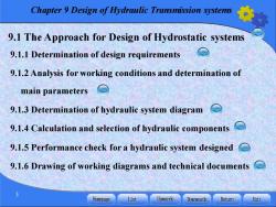
Chapter 9 Design of Hydraulic Transmission systems 9.1 The Approach for Design of Hydrostatic systems 9.1.1 Determination of design requirements 9.1.2 Analysis for working conditions and determination of main parameters 9.1.3 Determination of hydraulic system diagram 9.1.4 Calculation and selection of hydraulic components 9.1.5 Performance check for a hydraulic system designed 9.1.6 Drawing of working diagrams and technical documents 3 Homepage List Upwards Downwards Retumn Exit
Chapter 9 Design of Hydraulic Transmission systems 3 9.1 The Approach for Design of Hydrostatic systems 9.1.1 Determination of design requirements 9.1.2 Analysis for working conditions and determination of main parameters 9.1.3 Determination of hydraulic system diagram 9.1.4 Calculation and selection of hydraulic components 9.1.5 Performance check for a hydraulic system designed 9.1.6 Drawing of working diagrams and technical documents
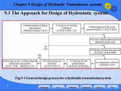
Chapter 9 Design of Hydraulic Transmission systems 9.1 The Approach for Design of Hydrostatic systems 1-Determination of design 2-Analysis of working conditions 3-Determination of the main requirements (明确液压系统设计要求) (分析液压系统工况) parameters(确定主要技术参数) 4-System scheme determination (确定液压系统方案) No (否) 5-Principle cincuits drawing out (拟定液压系统原理图) Yes (是) 8-Drawing out the working diagram All requirements are 7-Checking for the and technic documents satisfied? performances 6-Components selection (绘制工作图,编制技术文件) (是否符合要求?) (验算液压系统性能) (选择液压元件) Fig.9-1 General design process for a hydraulic transmission system Homepage List Upwards Downwards Retu Exit
Chapter 9 Design of Hydraulic Transmission systems 4 9.1 The Approach for Design of Hydrostatic systems Fig.9-1 General design process for a hydraulic transmission system

Chapter 9 Design of Hydraulic Transmission systems 9.1.1 Determination of design requirements Before a hydraulic system is designed,the working conditions of the mainframe in the mechanical equipment must be analyzed. 1.The purpose of the mainframe,the overall arrangement,the limitations to the position of the hydraulic devices and their sizes. 2.The mainframe work cycle,the system actions,their sequence, interlock function,automatization. 3.The load on actuators and the ranges of speed,motion stability position accuracy,conversion accuracy,etc. 4.Working environment and working conditions. 5.Working efficiency,safety,reliability,cost,etc Homepage List Upwards Downwards Retumn Exit
Chapter 9 Design of Hydraulic Transmission systems 5 9.1.1 Determination of design requirements Before a hydraulic system is designed, the working conditions of the mainframe in the mechanical equipment must be analyzed. 1. The purpose of the mainframe, the overall arrangement, the limitations to the position of the hydraulic devices and their sizes. 2. The mainframe work cycle, the system actions, their sequence, interlock function, automatization. 3. The load on actuators and the ranges of speed, motion stability, position accuracy, conversion accuracy, etc. 4. Working environment and working conditions. 5. Working efficiency, safety, reliability, cost, etc
Chapter 9 Design of Hydraulic Transmission systems 9.1.2 Analysis for working conditions and determination of main parameters Analysis of working conditions dynamic parameters(Fig.9-2a) Includes two parts of movement parameters(Fig.9-2b) 1)Dynamic parameters analysis A load diagram can be drawn out based on the determined extrinsic loads,see Fig.9-2a,which is load chart.The load chart is actually a load-displacement (F-1)curve Homepage List Upwards Downwards Retumn Exit
Chapter 9 Design of Hydraulic Transmission systems 6 1. Analysis of working conditions 1)Dynamic parameters analysis A load diagram can be drawn out based on the determined extrinsic loads, see Fig.9-2a, which is load chart. The load chart is actually a load-displacement (F-l)curve . dynamic parameters (Fig.9-2a) Includes two parts of movement parameters (Fig.9-2b) 9.1.2 Analysis for working conditions and determination of main parameters
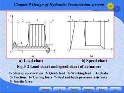
Chapter 9 Design of Hydraulic Transmission systems F a) b) a)Load chart b)Speed chart Fig.9-2 Load chart and speed chart of actuators 1-Startup acceleration 2-Quick feed 3-Working feed 4-Brake 5-Friction 6-Cutting force 7-Seal and back pressure resistance 8-Inertia force Homepage List Upwards Downwards Retumn Exit
Chapter 9 Design of Hydraulic Transmission systems 7 a) Load chart b) Speed chart Fig.9-2 Load chart and speed chart of actuators 1- Startup acceleration 2- Quick feed 3- Working feed 4- Brake 5- Friction 6- Cutting force 7- Seal and back pressure resistance 8-Inertia force

Chapter 9 Design of Hydraulic Transmission systems 2)Movement parameters analysis Fig.9-2b is a speed-displacement (v-1)curve drawn to express the speed of each actuator in different phases,it is called speed chart. When the actuator works in line reciprocating,the extrinsic load will be F=F+F+F (9-1) (1)The working load F Homepage List Upwards Downwards Retumn Exit
Chapter 9 Design of Hydraulic Transmission systems 8 2)Movement parameters analysis Fig.9-2b is a speed-displacement (v-l)curve drawn to express the speed of each actuator in different phases, it is called speed chart. When the actuator works in line reciprocating, the extrinsic load will be F F F F = + + L f a (9-1) (1) The working load FL
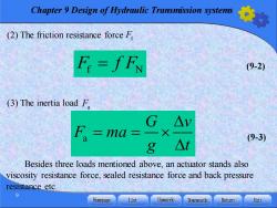
Chapter 9 Design of Hydraulic Transmission systems (2)The friction resistance force F F=fFN (9-2) (3)The inertia load F G△v F =ma= 一X (9-3) 8 △t Besides three loads mentioned above,an actuator stands also viscosity resistance force,sealed resistance force and back pressure resistance etc. Homepage List Upwards Downwards Retumn Exit
Chapter 9 Design of Hydraulic Transmission systems 9 (2) The friction resistance force Ff F f F f N = (9-2) (3) The inertia load Fa Besides three loads mentioned above, an actuator stands also viscosity resistance force, sealed resistance force and back pressure resistance etc. a (9-3) G v F ma g t = =
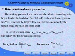
Chapter 9 Design of Hydraulic Transmission systems 2.Determination of main parameters The working pressure for actuators can be selected according to the largest load in the load chart(see Tab.9-1)or the mainframe type(see Tab.9-2).However the largest flow rate must be calculated by the highest speed shown in the speed chart. The lowest working speed vinor i(n=2min/60) must satisfy the following requirements: For cylinders ∠Vmin For motors qmin≤0min M 10 Homepage List Upwards Downwards Retumn Exit
Chapter 9 Design of Hydraulic Transmission systems 10 2. Determination of main parameters The working pressure for actuators can be selected according to the largest load in the load chart (see Tab.9-1) or the mainframe type (see Tab.9-2). However the largest flow rate must be calculated by the highest speed shown in the speed chart. The lowest working speed must satisfy the following requirements: min min q v A ≤ min min M q V For cylinders For motors ≤ min min min min v n or ( 2 = π / 60)
按次数下载不扣除下载券;
注册用户24小时内重复下载只扣除一次;
顺序:VIP每日次数-->可用次数-->下载券;
- 福州大学:《液压与气压传动》课程电子教案(PPT教学课件)Chapter 08 Examples of Hydraulic Systems.pptx
- 福州大学:《液压与气压传动》课程电子教案(PPT教学课件)Chapter 07 Basic Hydraulic Circuits.pptx
- 福州大学:《液压与气压传动》课程电子教案(PPT教学课件)Chapter 06 Auxiliary Components for Hydraulic Systems.pptx
- 福州大学:《液压与气压传动》课程电子教案(PPT教学课件)Chapter 05 Hydraulic Control Valves.pptx
- 福州大学:《液压与气压传动》课程电子教案(PPT教学课件)Chapter 04 Hydraulic Actuators.pptx
- 福州大学:《液压与气压传动》课程电子教案(PPT教学课件)Chapter 03 Hydraulic Pumps.pptx
- 福州大学:《液压与气压传动》课程电子教案(PPT教学课件)Chapter 02 Fundamental Hydraulic Fluid Mechanics.pptx
- 福州大学:《液压与气压传动》课程电子教案(PPT教学课件)Chapter 01 Introduction to Hydraulic and Pneumatic Transmission.pptx
- 福州大学:《液压与气压传动》课程电子教案(PPT教学课件)第12章 气动传动系统实例.pptx
- 福州大学:《液压与气压传动》课程电子教案(PPT教学课件)第11章 气动基本回路及其应用.pptx
- 福州大学:《液压与气压传动》课程电子教案(PPT教学课件)第10章 气源装置及气动元件.pptx
- 福州大学:《液压与气压传动》课程电子教案(PPT教学课件)第9章 液压系统的设计计算.pptx
- 福州大学:《液压与气压传动》课程电子教案(PPT教学课件)第8章 典型液压系统.pptx
- 福州大学:《液压与气压传动》课程电子教案(PPT教学课件)第7章 液压基本回路.pptx
- 福州大学:《液压与气压传动》课程电子教案(PPT教学课件)第6章 液压辅件.pptx
- 福州大学:《液压与气压传动》课程电子教案(PPT教学课件)第5章 液压控制阀.pptx
- 福州大学:《液压与气压传动》课程电子教案(PPT教学课件)第4章 液压马达与液压缸.pptx
- 福州大学:《液压与气压传动》课程电子教案(PPT教学课件)第3章 液压泵.pptx
- 福州大学:《液压与气压传动》课程电子教案(PPT教学课件)第2章 液压流体力学基础.pptx
- 福州大学:《液压与气压传动》课程电子教案(PPT教学课件)第1章 液压与气压传动概论.pptx
- 福州大学:《液压与气压传动》课程电子教案(PPT教学课件)Chapter 10 Air Supply Devices and Pneumatic Components.pptx
- 福州大学:《液压与气压传动》课程电子教案(PPT教学课件)Chapter 11 Basic Circuits and their Application.pptx
- 福州大学:《液压与气压传动》课程电子教案(PPT教学课件)Chapter 12 Pneumatics Transmission System Examples.pptx
- 《电机与电气控制技术》课程教学课件(打印版)第一章 磁路与变压器.pdf
- 福建船政交通职业学院:《机床电气设备运行与维护》课程试题库与答案(打印版).pdf
- 《电机与电气控制技术》课程教学课件(打印版)第二章 异步电动机及其电力拖动.pdf
- 《电机与电气控制技术》课程教学课件(打印版)第三章 直流电动机.pdf
- 《电机与电气控制技术》课程教学课件(打印版)第五章 常用低压电器.pdf
- 《电机与电气控制技术》课程教学课件(打印版)第六章 电气控制电路基本环节.pdf
- 福建船政交通职业学院:《机床电气设备运行与维护》课程实验项目指导书(打印版,共十八个实验,指导教师:王秋霞).pdf
- 呼和浩特职业学院:《电力机车控制》课程教学大纲(打印版).pdf
- 呼和浩特职业学院:《电力机车控制》课程教学实训标准(打印版).pdf
- 呼和浩特职业学院:《电力机车控制》课程教案讲义(打印版)第一章 电力机车原理.pdf
- 呼和浩特职业学院:《电力机车控制》课程教案讲义(打印版)第二章 直流电力机车速度调节.pdf
- 呼和浩特职业学院:《电力机车控制》课程教案讲义(打印版)第三章 电力机车的电气制动.pdf
- 呼和浩特职业学院:《电力机车控制》课程教案讲义(打印版)第四章 韶山4改电力机车主电路.pdf
- 呼和浩特职业学院:《电力机车控制》课程教案讲义(打印版)第五章 电力机车辅助电路.pdf
- 呼和浩特职业学院:《电力机车控制》课程教案讲义(打印版)第七章 电力机车的高低压试验.pdf
- 呼和浩特职业学院:《电力机车控制》课程教案讲义(打印版)第六章 SS4G电力机车控制电路.pdf
- 呼和浩特职业学院:《电力机车控制》课程教案讲义(打印版)第八章 SS4G型机车应急故障处理教案.pdf
