福州大学:《液压与气压传动》课程电子教案(PPT教学课件)Chapter 06 Auxiliary Components for Hydraulic Systems

Chmer Componats for Hr ym Chapter list 6.1 Accumulators 6.2 Filters习 6.3 Reservoirs 6.4 Piping/Tubing Connectors 6.5 Seals and Sealing Devices Homepage List Upwards Dowrwards Retun Exit
Chapter 6 Auxiliary Components for Hydraulic Systems 1 6.1 Accumulators 6.2 Filters 6.3 Reservoirs 6.4 Piping/Tubing Connectors 6.5 Seals and Sealing Devices Chapter list

Chaptery Compore for ram 6.1 Accumulators 6.1.1 Operating principles 6.1.2 Applications 6.1.3 Calculation of parameters Homepage List Upwards Downwards Retun Exit
Chapter 6 Auxiliary Components for Hydraulic Systems 2 6.1 Accumulators 6.1.1 Operating principles 6.1.2 Applications 6.1.3 Calculation of parameters

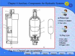
r6 Auxiliary Components for Hydraulic Systs 6.1 Accumulators 6.1.1 Operating principles There are three types of accumulators:spring loaded, weight loaded and charged gas.The common used are charged gas accumlators,which can be divided into piston type(Fig.6-1a) and bag type(Fig.6-1b). Fig.6-2 shows an accumulator,which basically consists of 4 parts:shell body 1,interlayer 3,compressible air 2(weight loaded or spring)on the upper of the interlayer and operating oil 4 located under the interlayer and connected with system.It includes two processes:filled in oil fluid(accumulation)and displacement out oil fluid(release) Homepage List Upwards Downward达 Return Exit
Chapter 6 Auxiliary Components for Hydraulic Systems 3 6.1 Accumulators 6.1.1 Operating principles There are three types of accumulators: spring loaded, weight loaded and charged gas. The common used are charged gas accumlators,which can be divided into piston type (Fig. 6-1a) and bag type (Fig. 6-1b). Fig. 6-2 shows an accumulator, which basically consists of 4 parts: shell body 1, interlayer 3, compressible air 2 (weight loaded or spring) on the upper of the interlayer and operating oil 4 located under the interlayer and connected with system. It includes two processes: filled in oil fluid (accumulation) and displacement out oil fluid (release)

Chapter 6 Auxiliary Components for Hydraulic Systems Play DVD a)Piston type 1-Piston 2-Cylinder 3-Gas valve Play D吧 b)Bag type 1-Gas valve 2-Steel shell 3-Bladder 4-Poppet valve b) Fig 6-1 Charged gas accumulator Homepage List Upwards Downward止 Return Exit
Chapter 6 Auxiliary Components for Hydraulic Systems 4 Fig. 6-1 Charged gas accumulator a) Piston type b) Bag type 1-Piston 2-Cylinder 3- Gas valve 1-Gas valve 2-Steel shell 3-Bladder 4-Poppet valve

Chapter 6 Auxiliary Components for Hydraulic Systems a) b) c) Fig.6-2 Operating principle of accumulator a)After displacement out oil fluid b)Filled in oil fluid c)Displacement out oil fluid 1-Shell 2-Compressible gas(or weight or spring)3-Interlayer 4-Operating fluid 5 Homepage List Upwards Downwards Retun Exit
Chapter 6 Auxiliary Components for Hydraulic Systems 5 Fig. 6-2 Operating principle of accumulator a) After displacement out oil fluid b) Filled in oil fluid c) Displacement out oil fluid 1-Shell 2- Compressible gas ( or weight or spring) 3-Interlayer 4-Operating fluid

Chapter 6 Auxiliary Components for Hydraulic Systems It includes two processes:filled in oil fluid (accumulation)and discharging out oil fluid(release). 1.Filled in oil fluid(accumulation) It is an equilibrium state of pressure difference on the two sides of upper and down on the interlayer with the operating oil volume as V1 after displacement out oil fluid (release)shown in Fig.6-2a. When operating oil pressure in the accumulator is increased with the oil pressure in hydraulic system,the interlayer losses equilibrium and moves up under the action of operating difference,as shown in Fig.6-2b. Homepage List Upwards Downwards Retumn Exit
Chapter 6 Auxiliary Components for Hydraulic Systems 6 1. Filled in oil fluid (accumulation) It is an equilibrium state of pressure difference on the two sides of upper and down on the interlayer with the operating oil volume as V1 after displacement out oil fluid (release) shown in Fig. 6-2a. When operating oil pressure in the accumulator is increased with the oil pressure in hydraulic system,the interlayer losses equilibrium and moves up under the action of operating difference, as shown in Fig. 6-2b. It includes two processes: filled in oil fluid (accumulation) and discharging out oil fluid (release)

Chapter 6 Auxiliary Components for Hydraulic Systems 2.Discharging out oil fluid(release) When the system pressure is lower than the pressure of the operating oil,the interlay is moved down under the action of gas pressure(or weight loaded or spring loaded);at the same time oil is discharged out of the accumulator and flows into the system until a new pressure equilibrium on the two sides of the interlayer as shown in Fig.6-2c. 6.1.2 Applications Such an accumulator can be used to advantage in a number of hydraulic applications: 1)To supply oil lost through leakage in a system held under pressure but not operating for long periods.To serve as an auxiliary or emergency source of hydraulic power where pump Homepage List Upwards Downward达 Return Exit
Chapter 6 Auxiliary Components for Hydraulic Systems 7 2. Discharging out oil fluid (release) When the system pressure is lower than the pressure of the operating oil, the interlay is moved down under the action of gas pressure (or weight loaded or spring loaded); at the same time oil is discharged out of the accumulator and flows into the system until a new pressure equilibrium on the two sides of the interlayer as shown in Fig. 6-2c. 6.1.2 Applications Such an accumulator can be used to advantage in a number of hydraulic applications: 1) To supply oil lost through leakage in a system held under pressure but not operating for long periods. To serve as an auxiliary or emergency source of hydraulic power where pump

Chapter 6 Auxiliary Components for Hydraulic Systems or feed line have failed.To operate a secondary circuit intermittently in connection with a constant duty primary circuit without affecting the speed or loading of the primary circuit. To compensate for expanding and contracting volumes due to thermal changes. 2)To supply holding pressure where the operating cycle calls for pressure to be applied for a long periods of time.For example, an accumulator can be used to avoid accident when the pump fails randomicity at starting. 3)To absorb pulsations,surges,or shocks from reciprocating pumps or quick closing valves.To cushion and lower the noise the load on fork lifts,front end loaders,backhoes,etc 8 Homepage List Upwards Downwards Return Exit
Chapter 6 Auxiliary Components for Hydraulic Systems 8 or feed line have failed. To operate a secondary circuit intermittently in connection with a constant duty primary circuit without affecting the speed or loading of the primary circuit. To compensate for expanding and contracting volumes due to thermal changes. 2) To supply holding pressure where the operating cycle calls for pressure to be applied for a long periods of time. For example, an accumulator can be used to avoid accident when the pump fails randomicity at starting. 3) To absorb pulsations, surges, or shocks from reciprocating pumps or quick closing valves. To cushion and lower the noise the load on fork lifts, front end loaders, backhoes, etc

Chapter 6 Auxiliary Components for Hydraulic Systems 6.1.3 Calculation of parameters 1.Calculation for the charged gas volume o The volume of an accumulator is the charged gas volume for a bag accumulator p%”=p”=p2V” -Constant (6-1) (1)For the isothermal changes The involvement no change in temperature,and no internal energy changes occur in the gas.Take n=1,then △V 6-2) p.( Homepage List Upwards Dowrwards Return Exit
Chapter 6 Auxiliary Components for Hydraulic Systems 9 6.1.3 Calculation of parameters 1. Calculation for the charged gas volume V0 The volume of an accumulator is the charged gas volume for a bag accumulator 0 0 1 1 2 2 n n n p V p V p V = = =Constant (6-1) (1) For the isothermal changes The involvement no change in temperature, and no internal energy changes occur in the gas. Take n=1, then 0 0 1 2 ( ) 1 1 V V p p p = − (6-2)

r 6 Auxiliary Components for Hydraulic Sys (2)For the adiabatic(isentropic)changes The other bounding condition is a reversible adiabatic (isentropic)change which takes place so rapidly that no flow of heat into or out of the gas occurs.The defining relationship is △V Vo三1 -(写 1 (6-3) p (3)For polytropic changes Practically accumulator gas can follow any number of polytropic changed,which is isothermal during accumulating and adiabatic during discharging due to gas expanded.It can be so calculated by 10 Homepage List Upwards Downwards Return Exit
Chapter 6 Auxiliary Components for Hydraulic Systems 10 0 0 1 1 1 1 2 1 1 [( ) ( ) ] n n n V V p p p = − (2)For the adiabatic(isentropic)changes The other bounding condition is a reversible adiabatic (isentropic) change which takes place so rapidly that no flow of heat into or out of the gas occurs. The defining relationship is (3) For polytropic changes Practically accumulator gas can follow any number of polytropic changed, which is isothermal during accumulating and adiabatic during discharging due to gas expanded. It can be so calculated by (6-3)
按次数下载不扣除下载券;
注册用户24小时内重复下载只扣除一次;
顺序:VIP每日次数-->可用次数-->下载券;
- 福州大学:《液压与气压传动》课程电子教案(PPT教学课件)Chapter 05 Hydraulic Control Valves.pptx
- 福州大学:《液压与气压传动》课程电子教案(PPT教学课件)Chapter 04 Hydraulic Actuators.pptx
- 福州大学:《液压与气压传动》课程电子教案(PPT教学课件)Chapter 03 Hydraulic Pumps.pptx
- 福州大学:《液压与气压传动》课程电子教案(PPT教学课件)Chapter 02 Fundamental Hydraulic Fluid Mechanics.pptx
- 福州大学:《液压与气压传动》课程电子教案(PPT教学课件)Chapter 01 Introduction to Hydraulic and Pneumatic Transmission.pptx
- 福州大学:《液压与气压传动》课程电子教案(PPT教学课件)第12章 气动传动系统实例.pptx
- 福州大学:《液压与气压传动》课程电子教案(PPT教学课件)第11章 气动基本回路及其应用.pptx
- 福州大学:《液压与气压传动》课程电子教案(PPT教学课件)第10章 气源装置及气动元件.pptx
- 福州大学:《液压与气压传动》课程电子教案(PPT教学课件)第9章 液压系统的设计计算.pptx
- 福州大学:《液压与气压传动》课程电子教案(PPT教学课件)第8章 典型液压系统.pptx
- 福州大学:《液压与气压传动》课程电子教案(PPT教学课件)第7章 液压基本回路.pptx
- 福州大学:《液压与气压传动》课程电子教案(PPT教学课件)第6章 液压辅件.pptx
- 福州大学:《液压与气压传动》课程电子教案(PPT教学课件)第5章 液压控制阀.pptx
- 福州大学:《液压与气压传动》课程电子教案(PPT教学课件)第4章 液压马达与液压缸.pptx
- 福州大学:《液压与气压传动》课程电子教案(PPT教学课件)第3章 液压泵.pptx
- 福州大学:《液压与气压传动》课程电子教案(PPT教学课件)第2章 液压流体力学基础.pptx
- 福州大学:《液压与气压传动》课程电子教案(PPT教学课件)第1章 液压与气压传动概论.pptx
- 福州大学:《液压与气压传动》课程授课教案 Hydraulic and Pneumatic Transmission(英文讲义,负责人:陈淑梅).pdf
- 福州大学:《液压与气压传动》课程试卷及参考答案(英文).pdf
- 福州大学:《液压与气压传动》课程作业习题(英文,无答案).pdf
- 福州大学:《液压与气压传动》课程电子教案(PPT教学课件)Chapter 07 Basic Hydraulic Circuits.pptx
- 福州大学:《液压与气压传动》课程电子教案(PPT教学课件)Chapter 08 Examples of Hydraulic Systems.pptx
- 福州大学:《液压与气压传动》课程电子教案(PPT教学课件)Chapter 09 Design of Hydraulic Transmission systems.pptx
- 福州大学:《液压与气压传动》课程电子教案(PPT教学课件)Chapter 10 Air Supply Devices and Pneumatic Components.pptx
- 福州大学:《液压与气压传动》课程电子教案(PPT教学课件)Chapter 11 Basic Circuits and their Application.pptx
- 福州大学:《液压与气压传动》课程电子教案(PPT教学课件)Chapter 12 Pneumatics Transmission System Examples.pptx
- 《电机与电气控制技术》课程教学课件(打印版)第一章 磁路与变压器.pdf
- 福建船政交通职业学院:《机床电气设备运行与维护》课程试题库与答案(打印版).pdf
- 《电机与电气控制技术》课程教学课件(打印版)第二章 异步电动机及其电力拖动.pdf
- 《电机与电气控制技术》课程教学课件(打印版)第三章 直流电动机.pdf
- 《电机与电气控制技术》课程教学课件(打印版)第五章 常用低压电器.pdf
- 《电机与电气控制技术》课程教学课件(打印版)第六章 电气控制电路基本环节.pdf
- 福建船政交通职业学院:《机床电气设备运行与维护》课程实验项目指导书(打印版,共十八个实验,指导教师:王秋霞).pdf
- 呼和浩特职业学院:《电力机车控制》课程教学大纲(打印版).pdf
- 呼和浩特职业学院:《电力机车控制》课程教学实训标准(打印版).pdf
- 呼和浩特职业学院:《电力机车控制》课程教案讲义(打印版)第一章 电力机车原理.pdf
- 呼和浩特职业学院:《电力机车控制》课程教案讲义(打印版)第二章 直流电力机车速度调节.pdf
- 呼和浩特职业学院:《电力机车控制》课程教案讲义(打印版)第三章 电力机车的电气制动.pdf
- 呼和浩特职业学院:《电力机车控制》课程教案讲义(打印版)第四章 韶山4改电力机车主电路.pdf
- 呼和浩特职业学院:《电力机车控制》课程教案讲义(打印版)第五章 电力机车辅助电路.pdf
