《电路》课程参考书籍(ELCTRIC CIRCUIT)CAPTER 10 Non-sinusoidal excited circuit analysis

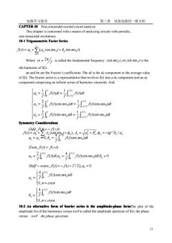
电路学习指导 第三章电阻电路的一般分析 CAPTER 10 Non-sinusoidal excited circuit analysis This chapter is concerned with a means of analyzing circuits with periodic, non-sinusoidal excitations. 10-1 Trigonometric Forier Series f(1)= a+∑(a, cosnot+b,sin no。1) Where =2/ is caled the fundamental frequency cos no, or, sin no is the nth harmonic of f(t). an and bn are the Fourier's coefficients. The a0 is the de component or the average value of f(t). The fourier series is a representation that revolves f(t) into a de component and an ac component comprising an infinite series of harmonic sinusoids. And: a =TI'rndr=sndan a.'nncos noordr =f.sncos mordn a.I5'nsim morordr =sin mo odin Symmetry Considerations Odd,f(A=-f(-1) f()=a+∑A,cos(nunt+n),An=a2n+b2,n=-tg-b,Ia a=a=0,b=()sin notd Even,f(1)=f(-1) ao-I1m undna.4fm nuncosme ondl b,-=0 Half-wave,)=-(1-T12),a.=0 a.sor 0,n=even as r imnon 0.n=even 10-2 An alternative form of fourier series is the amplitude-phase formThe plot of the amplitude An of the harmonics versus nwis called the amplitude spectrum of f(t), the phase versus nw0 the phase spectrum 21
电路学习指导 第三章 电阻电路的一般分析 21 CAPTER 10 Non-sinusoidal excited circuit analysis This chapter is concerned with a means of analyzing circuits with periodic , non-sinusoidal excitations. 10-1 Trigonometric Trigonometric Trigonometric Trigonometric Forier Series Where T ω = 2π is called the fundamental frequency n t or n t 0 0 cos ω , ,sin ω is the nth harmonic of f(t). an and bn are the Fourier’s coefficients. The a0 is the dc component or the average value of f(t). The fourier series is a representation that revolves f(t) into a dc component and an ac component comprising an infinite series of harmonic sinusoids. And: Symmetry Symmetry Symmetry Symmetry Considerations Considerations Considerations Considerations 10-2 An alternative alternative alternative alternative form of fourier fourier fourier fourier series is the amplitude-phase amplitude-phase amplitude-phase amplitude-phase formThe plot of the amplitude An of the harmonics versus nw0 is called the amplitude spectrum of f(t), the phase versus nw0 the phase spectrum. ∑ ∞ = = + + 1 0 0 0 ( ) ( cos sin ) n n n f t a a nω t b nω t ⎪ ⎪ ⎪ ⎩ ⎪ ⎪ ⎪ ⎨ ⎧ = = = = = = ∫ ∫ ∫ ∫ ∫ ∫ − − − T T T n T T T n T T T f t n tdt T f t n tdt T a f t n tdt T f t n tdt T a f t dt T f t dt T a 0 / 2 / 2 0 0 0 / 2 / 2 0 0 0 / 2 / 2 0 ( )sin 1 ( )sin 2 ( ) cos 1 ( ) cos 2 ( ) 1 ( ) 1 ω ω ω ω ( ) cos , 0 4 ( ) , 2 , ( ) ( ) / 2 0 0 / 2 0 0 = = = = − ∫ ∫ n T n T f t n tdt b T f t dt a T a Even f t f t ω ∫ = = = = − − / 2 0 0 0 ( )sin 4 0, , ( ) ( ) T n n f t n tdt T a a b Odd f t f t ω ⎪ ⎩ ⎪ ⎨ ⎧ = = ⎪ ⎩ ⎪ ⎨ ⎧ = = − = − − = ∫ ∫ n even f t n tdt b T n even f t n tdt a T Half wave f t f t T a T n T n 0, ( )sin 4 0, ( ) cos 4 , ( ) ( / 2), 0 / 2 0 0 / 2 0 0 0 ω ω ∑ ∞ = − = + + = + = − 1 2 2 1 0 0 ( ) cos( ), , / n n n n n n n bn an f t a A nω t φ A a b φ tg

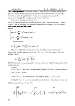
电路学习指导 第三章电阻电路的一般分析 10 CrewirappllcadonWe find that in practice,many circuits are driven by nonsinusoidal periodic functions.To find the steady-state response of a circuit to a nonsinusoidal periodic excitation.requires the application of a Fourier series.ac phasor analysis.and the superposition principle.The procedure usually involves three steps. 1 Express the excitation as a Fourier series 2 Find the response of each term in the Fourier series(in the frequency domain or phasor domain)3 Add the individual response using the superposition principle(in the time domain). 10-4Average power and RMS values suppose M0=U+∑UnN2cos(m1-0) 0=1+∑n2cos(o,1-,) Average power is: P=wh=n+2U以cos0.-) This shows that the total average power is the sum of the average powers in each harmonically related voltage and current.And the rms (root-meat-square)value or the effective value is: 1-h-+空公 E10-1 Determine the symmetry property of the waves shown in Fig.E10-1,and specify which coefficient is zero Solution To Fig E10-1 a,it is an even and odd harmonic function.Symmetry:axis and half-wave ∴.6=0,=0,2=0: To Fig E10-1 b,it is an odd function.Symmetry:the origin.=0,=0 To Fig.E10-1 c,it is an odd and odd harmonic function.Symmetry:the origin.and half-wave.d=0=0,=0; 4人
电路学习指导 第三章 电阻电路的一般分析 22 10-3 Circuit Circuit Circuit Circuit application application application applicationWe find that in practice , many circuits are driven by nonsinusoidal periodic functions. To find the steady-state response of a circuit to a nonsinusoidal periodic excitation , requires the application of a Fourier series , ac phasor analysis, and the superposition principle. The procedure usually involves three steps. 1 Express the excitation as a Fourier series 2 Find the response of each term in the Fourier series (in the frequency domain or phasor domain) 3 Add the individual response using the superposition principle (in the time domain). 10-4 Average Average Average Average power and RMS values suppose Average power is : This shows that the total average power is the sum of the average powers in each harmonically related voltage and current. And the rms (root-meat-square) value or the effective value is: E10-1 Determine the symmetry property of the waves shown in Fig.E10-1, and specify which coefficient is zero. Solution To Fig.E10-1 a , it is an even and odd harmonic function. Symmetry: axis and half-wave ∴ a0 = 0 , bk = 0 , a2k = 0 ; To Fig.E10-1 b , it is an odd function. Symmetry:the origin. ∴ a0 = 0 , ak = 0 To Fig.E10-1 c, it is an odd and odd harmonic function . Symmetry:the origin. and half-wave∴ a0 = 0 , ak = 0 , b2k = 0 ; ∫ ∑ ∞ = = = + 1 2 2 0 0 1 2 n n T i dt I I T I cos( ) 1 0 1 n n T n n n uidt UI U I T P = = + θ −φ ∫ ∑ ∞ = ⎪ ⎪ ⎩ ⎪ ⎪ ⎨ ⎧ = + − = + − ∑ ∑ ∞ = ∞ = 1 0 1 0 ( ) 2 cos( ) ( ) 2 cos( ) n n n n n n i t I I n t u t U U n t ω φ ω θ

电路学习指导 第三章电阻电路的一般分析 Fig.E10-1 a F1g.E10-1b Fig.E10-1 c E10-2 Determine the Fourier series of the wave shown in Fig.10-2. 无 :u V Fig.El0-2 Fig.E10-3 Solution:The expression of (is:()= -Un 子s7 Because it is an odd and odd harmonic function:origin.and half-wave symmetry .am=0,ak=0,bf=0 4-V.snko.lco.-治sinkm.o0 kπ1 -2osto水6=l35 kπ 元 E10-3 The circuit is as Fig.E10-3,determine the readings of the voltmeter,ammeter and wattmeter.Where =10+141.4cos@1/+28.28cos(301/+30)V, i=10cos(11+45)+2c0s(3011-15)A Solution: /=102+1002+202=102.5V -周-2w P=B+月+乃=0+100×7.071×cos(-45)+20×V2cos(30°+15)=520W So the readings of the voltmeter,ammeter and wattmeter 102.5V,7.21A and 520W. respectively. E10-4 The circuit is shown as Fig.E10-4,determine and its effective value.Where 23
电路学习指导 第三章 电阻电路的一般分析 23 Fig.E10-1 a Fig.E10-1 b Fig.E10-1 c E10-2 Determine the Fourier series of the wave shown in Fig.10-2. Fig.E10-2 Fig.E10-3 Solution:The expression of f (t) is: ⎪ ⎪ ⎩ ⎪⎪ ⎨ ⎧ − ≤ ≤ ≤ ≤ = t T T U T U t f t 2 2 0 ( ) m m Because it is an odd and odd harmonic function .: origin. and half-wave symmetry ∴ a0 = 0 , ak = 0 , b2k = 0 sin k d( ) k 2 sin k d( ) 2 1 π 0 1 m 1 π 0 m 1 t k t U b U t t k ω ω π ω ω π ∫ ∫ = = [ cosk ] 1,3,5⋯ k 2 1 0 m = − k = π t U ω π kπ 4U m = ⎥ ⎦ ⎤ ⎢ ⎣ ⎡ = t + t + t +. U f t 1 1 1 m sin 5 5 1 sin 3 3 1 sin 4 ( ) ω ω ω π E10-3 The circuit is as Fig.E10-3,determine the readings of the voltmeter, ammeter and wattmeter. Where u =10 +141.4cosω1t + 28.28cos(3ω1t + 30°)V , i =10cos(ω1t + 45°) + 2cos(3ω1t −15°)A . Solution: 10 100 20 102.5V 2 2 2 U = + + = 7.21A 2 2 2 10 2 2 = ⎟ ⎟ ⎠ ⎞ ⎜ ⎜ ⎝ ⎛ + ⎟ ⎟ ⎠ ⎞ ⎜ ⎜ ⎝ ⎛ I = P = P0 + P1 + P3 = 0 +100×7.071×cos(−45°) + 20× 2 cos(30° +15°) = 520W So the readings of the voltmeter, ammeter and wattmeter 102.5V,7.21A and 520W, respectively. E10-4 The circuit is shown as Fig.E10-4, determine u and its effective value. Where

电路学习指导 第三章电阻电路的一般分析 o1=50rads,s=10+100W2coso1+50W2cos(3011+30)V 12 12 12 12 9 ①us1nl0.1H u ①Us(o,1n U(o) (a) (b) 1019b 12a1 Dus)1 jx U ①Us3)1njX3 U3) (c) (d) 图11-4例题114图 Solution: We calculate the DC,fundamental and the third harmonic wave,and the equivalent circuit are shown as Fig.E10-4b,Fig.E10-4c and Fig E10-4d,respectively In Fig.E10-4b Uso)=10V,U(0)=0. In Fig.E10-4c0=100∠0V,Km=o1L=50×0.1=5Q. the nodal equations are: a:30aw-w=100 b:-w++ thus U=U)=47.89216.7V In Fig E10-4cde=50∠30V,K)=3o1L=3×50×0.1=152 the nodal equations are ①:303)-03)=50∠30° ②:-0)+(1+ thus:0==24.88∠35.74V 1=47.89√2(coso11+16.7)+24.882cos(301+35.74V the effective value is U=+=02+47.892+24.882 =53.79V 10-7 Problems
电路学习指导 第三章 电阻电路的一般分析 24 ω1 = 50rad/s ,uS =10 +100 2 cosω1t + 50 2 cos(3ω1t + 30°)V . (a) (b) (c) (d) 图 11-4 例题 11-4 图 Solution: We calculate the DC, fundamental and the third harmonic wave , and the equivalent circuit are shown as Fig.E10-4b, Fig.E10-4c and Fig.E10-4d, respectively In Fig.E10-4b US(0) =10V , U(0) = 0。 In Fig.E10-4c U̇S(1) =100∠0°V , X L(1) =ω1L = 50× 0.1 = 5Ω 。 the nodal equations are : a:3Ua(1) −Ub(1) =100 ̇ ̇ b: ) 0 j5 1 −Ua(1) + (1+ Ub(1) = ̇ ̇ thus U̇ (1) =U̇ b(1) = 47.89∠16.7°V In Fig.E10-4cd U̇S(3) = 50∠30°V , X L(3) = 3ω1L = 3×50×0.1=15Ω the nodal equations are ①:3Ua(3) −Ub(3) = 50∠30° ̇ ̇ ②: ) 0 j15 1 −U̇ a(3) + (1+ U̇ b(3) = thus:U̇ (3) =U̇ b(3) = 24.88∠35.74°V ∴u = 47.89 2(cosω1t +16.7°) + 24.88 2 cos(3ω1t + 35.74°)V the effective value is 0 47.89 24.88 53.79V 2 2 2 2 (3) 2 (1) 2 U = U(0) +U +U = + + = 10-7 Problems Problems Problems Problems

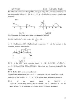
电路学习指导 第三章电阻电路的一般分析 P10-1 The half period wave of a signal has been given in Fig.P10-1,draw the complete wave in a period according:(1)=0:(2)=0:(3)a=0:(4)when is even,aand Bare both zeros Fig P10-1 Fig P10-2 P10-2 Determine the Fourier series of the wave shown in Fig.P10-2. P10-3 In Fig.P10-3,R=122,o1L=22, =180, ,C =10+80(+/,determine i and the readings of the voltmeter,ammeter and wattmeter. R 0 A Fig.P10-3 P10-4 In the RLC series connected circuit,R=11,L=0.015H,C=70u F, =11+141.4cos(1000/)-35.4sin(2000/V,determine and the power dissipated by the circuit. P10-5 In the RLC series connected circuit, )=100cos(314)+50cos(9421-30)V,0=10cos314)+1.755cos(9421-03)A. Determine:(1)the value ofRLC:(2):(3)the power dissipated by the circuit P10-6 In the circuit shown in Fig.10-6 us(/)=50+100sin(314/)-40cos(628/)+10sin(942/+20)V determine and the power delivered by the source and the effective value of the voltage and current 25
电路学习指导 第三章 电阻电路的一般分析 25 P10-1 The half period wave of a signal has been given in Fig.P10-1,draw the complete wave in a period according : (1) a0 = 0;(2) bk = 0 ;(3) ak = 0 ;(4)when k is even , a k and b k are both zeros. Fig.P10-1 Fig.P10-2 P10-2 Determine the Fourier series of the wave shown in Fig.P10-2. P10-3 In Fig.P10-3, R =12Ω,ω1L = 2Ω , =18Ω 1 ω1C , u =10 + 80 2(cosω1t + 30°) +18 2 cos3ω1tV , determine i and the readings of the voltmeter , ammeter and wattmeter. Fig.P10-3 P10-4 In the RLC series connected circuit , R =11Ω , L = 0.015H , C = 70μ F , u =11+141.4cos(1000t) − 35.4sin(2000t)V ,determine i and the power dissipated by the circuit. P10-5 In the RLC series connected circuit, u(t) =100cos(314t) + 50cos(942t − 30°)V ,i(t) =10cos(314t) +1.755cos(942t −θ3 )A . Determine ;(1) the value of R 、 L 、C ;(2)θ 3 ;(3) the power dissipated by the circuit. P10-6 In the circuit shown in Fig.10-6 , uS (t) = 50 +100sin(314t) − 40cos(628t) +10sin(942t + 20°)V determine i and the power delivered by the source and the effective value of the voltage and current

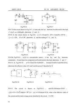
电路学习指导 第三章电阻电路的一般分析 1000.01m1 2 50m1a L() 、50pC 0.1H3L1 Fig.P10-6 Fig.P10-7 P10-7 In the circuit shown in Fig.10-7,if want only the 4 harmonic be delivered to the load. C=lu F,=1000rad/s,determine and P10-8 In the circuit shown in Fig 10-8./s=5+10cos(10/-20)+5sin(30/+60)A, ==2H,M=0.5H,determine u and the reading of A,and V2. A -N- L26(3 1(t Fig.P10-8 Fig.P10-9 P10-9In Fig P10-9,us()is a non-periodic source,it has 301 and 7 harmonic component,if want these two component not be delivered to the load,determine and C. P10-10 n Fig.P10-10, u=10+10sin314t+5sin942tV,=4sin(314t-元/6)+2sin(942t-元/3)A determine the effective value of U and I and the power P absorbed by N. 0 Fig.P10-10 Fig.P10-11 Fig.P10-12 P10-11 The circuit is shown as Fig.P10-11,u(t)=50+300sin(@t+30)V, ()=10+152 sin(/-30),iz(t )=8.93sin(t-10)A.what is the effective value of the current and the total average power absorbed by the circuit.(3.12W)
电路学习指导 第三章 电阻电路的一般分析 26 Fig.P10-6 Fig.P10-7 P10-7 In the circuit shown in Fig.10-7,if want only the 4ω1 harmonic be delivered to the load, C =1μ F,ω =1000rad/s, determine L1 and L2 . P10-8 In the circuit shown in Fig.10-8, iS = 5 +10cos(10t − 20°) + 5sin(30t + 60°)A , L1 = L2 = 2H , M = 0.5H , determine u2 and the reading of A ,and V2 . Fig.P10-8 Fig.P10-9 P10-9In Fig.P10-9 , uS (t) is a non-periodic source , it has 3ω1 and 7ω1 harmonic component,if want these two component not be delivered to the load, determine L and C . P10-10 In Fig.P10-10 , u=10+10sin314t+5sin942tV , I=4sin(314t-π/6)+2sin(942t-π/3)A, determine the effective value of U and I and the power P absorbed by N. i u N Z 2 Z 1 i 2 i 1 i R L i u Fig.P10-10 Fig.P10-11 Fig.P10-12 P10-11 The circuit is shown as Fig.P10-11 , u(t)=50+300sin(ωt+30o)V , i t t A o ( ) 10 15 2 sin( 30 ) 1 = + ω − ,i2(t )= 8.93sin(ωt-10o)A, what is the effective value of the current and the total average power absorbed by the circuit.(3.12W)

电路学习指导 第三章电阻电路的一般分析 P10-12 The circuit is shown as Fig.P10-12,i=2+22sinot+2sin3otA,R=30,oL=20,determine u(t)and the power absorbed by R (27W). 27
电路学习指导 第三章 电阻电路的一般分析 27 P10-12 The circuit is shown as Fig.P10-12,i=2+22sinωt+2sin3ωtA,R=3Ω, ωL=2Ω , determine u(t) and the power absorbed by R(27W)
按次数下载不扣除下载券;
注册用户24小时内重复下载只扣除一次;
顺序:VIP每日次数-->可用次数-->下载券;
- 《电路》课程参考书籍(ELCTRIC CIRCUIT)CAPTER 9 Magnetically Coupled Circuit.pdf
- 《电路》课程参考书籍(ELCTRIC CIRCUIT)CAPTER 8 THREE PHASE CIRCUIT.pdf
- 《电路》课程参考书籍(ELCTRIC CIRCUIT)CAPTER 7 SINUSOIDAL STEADY-STATE ANALYSIS.pdf
- 《电路》课程参考书籍(ELCTRIC CIRCUIT)CAPTER 6 SINUSOIDSAND PHASORS.pdf
- 《电路》课程参考书籍(ELCTRIC CIRCUIT)CAPTER5 OPERATIONALAMPLIFIER.pdf
- 《电路》课程参考书籍(ELCTRIC CIRCUIT)CAPTER4 CIRCUIT THEOREMS.pdf
- 《电路》课程参考书籍(ELCTRIC CIRCUIT)CAPTER3 THE SYSTEM ANALYSIS OF RESISTANCE CIRCUIT.pdf
- 《电路》课程参考书籍(ELCTRIC CIRCUIT)CHAPTER1 THE CIRCUIT ELEMENTS AND FUNDAMENTAL LAWS、CHAPTER 2 EQUIVALENT CIRCUIT OF RESISTOR CIRCUIT.pdf
- 新疆大学:《电路》课程教学大纲(自动化专业,汉).doc
- 新疆大学:《电路》课程教学大纲(电气专业,汉).doc
- 新疆大学:《电力系统分析》课程教学课件(暂态部分)第三章 电力系统三相短路电流的实用计算.pdf
- 新疆大学:《电力系统分析》课程教学课件(暂态部分)第二章 同步发电机突然三相短路分析.pdf
- 新疆大学:《电力系统分析》课程教学课件(暂态部分)第一章 电力系统故障分析的基本知识.pdf
- 新疆大学:《电力系统分析》课程教学课件(稳态部分)第六章 电力系统无功功率和电压调整.pdf
- 新疆大学:《电力系统分析》课程教学课件(稳态部分)第五章 电力系统有功功率与频率的调整.pdf
- 新疆大学:《电力系统分析》课程教学课件(稳态部分)第四章 复杂电力系统潮流的计算机算法.pdf
- 新疆大学:《电力系统分析》课程教学课件(稳态部分)第三章 简单电力网络的计算和分析.pdf
- 新疆大学:《电力系统分析》课程教学课件(稳态部分)第二章 电力系统元件模型和参数计算.pdf
- 新疆大学:《电力系统分析》课程教学课件(稳态部分)第一章 电力系统的基本概念.pdf
- 《电力系统分析》课程教学资源(学习资料)常见变压器参数(常见T参数).doc
- 《电路》课程学习指导(含题解,d220d25ec3d145f995e5a52aaa4cab20)第一章 电路的基本概念和基本定律.doc
- 《电路》课程学习指导(含题解,d220d25ec3d145f995e5a52aaa4cab20)第二章 电阻电路的等效变换.doc
- 《电路》课程学习指导(含题解,d220d25ec3d145f995e5a52aaa4cab20)第七章 相量法.doc
- 《电路》课程学习指导(含题解,d220d25ec3d145f995e5a52aaa4cab20)第三章 电阻电路的一般分析.doc
- 《电路》课程学习指导(含题解,d220d25ec3d145f995e5a52aaa4cab20)第九章 含有耦合电感的电路.doc
- 《电路》课程学习指导(含题解,d220d25ec3d145f995e5a52aaa4cab20)第五章 含有运算放大器的电阻电路.doc
- 《电路》课程学习指导(含题解,d220d25ec3d145f995e5a52aaa4cab20)第八章 正弦稳态电路的分析.doc
- 《电路》课程学习指导(含题解,d220d25ec3d145f995e5a52aaa4cab20)第十一章 非正弦周期电流电路.doc
- 《电路》课程学习指导(含题解,d220d25ec3d145f995e5a52aaa4cab20)第十二章 二端口网络.doc
- 《电路》课程学习指导(含题解,d220d25ec3d145f995e5a52aaa4cab20)第十章 三相电路.doc
- 《电路》课程学习指导(含题解,d220d25ec3d145f995e5a52aaa4cab20)第四章 电路定理.doc
- 《电路》课程学习指导(含题解,d220d25ec3d145f995e5a52aaa4cab20)第六章 非线性电阻电路.doc
- 《电路》课程学习指导(含题解,d220d25ec3d145f995e5a52aaa4cab20)第十七章 电路方程的矩阵形式.doc
- 《电路》课程学习指导(含题解,d220d25ec3d145f995e5a52aaa4cab20)第十三章 一阶电路.doc
- 《电路》课程学习指导(含题解,d220d25ec3d145f995e5a52aaa4cab20)第十五章 动态电路的复频域求解.doc
- 《电路》课程学习指导(含题解,d220d25ec3d145f995e5a52aaa4cab20)第十八章 均匀传输线.doc
- 《电路》课程学习指导(含题解,d220d25ec3d145f995e5a52aaa4cab20)第十六章 网络函数.doc
- 《电路》课程学习指导(含题解,d220d25ec3d145f995e5a52aaa4cab20)第十四章 二阶电路.doc
- 南阳师范学院:《电子电路CAD技术》课程电子教案(PPT课件)第一章 概论.ppt
- 南阳师范学院:《电子电路CAD技术》课程电子教案(PPT课件)第七章 逻辑模拟和数模混合模拟.ppt
