《电路》课程参考书籍(ELCTRIC CIRCUIT)CAPTER 9 Magnetically Coupled Circuit
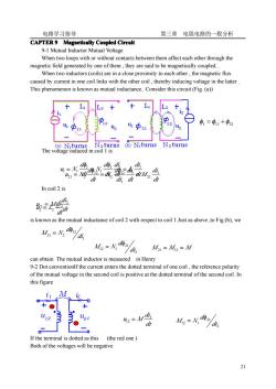
电路学习指导 第三章电阻电路的一般分析 CAPTER 9 Magnetically Coupled Circuit 9-1 Mutual Inductor Mutual Voltage When two loops with or without contacts between them affect each other through the magnetic field generated by one of them, they are said to be magnetically coupled. When two inductors(coils)are in a close proximity to each other, the magnetic flux caused by current in one coil links with the other coil, thereby inducing voltage in the latter. This phenomenon is known as mutual inductance. Consider this circuit (Fig. (a) + L1 L2 + + L1 L2 11 12 U1 12 U1 22 1=11+中12 11 12 21 A U2 (a) N1turns N2turns (b) Niturns N2turns The voltage induced in coil 1 is do dì In coil 2 is is known as the mutual inductance of coil 2 with respect to coil 1.Just as above,to Fig.(b), we M21=N22/d d21 M12=N12ydi,M21=M12=M can obtain The mutual inductor is measured in Henry 9-2 Dot conventionIf the current enters the dotted terminal of one coil, the reference polarity of the mutual voltage in the second coil is positive at the dotted terminal of the second coil. In this figure i1 M 12 A 0 0 + ○ + ○ 11 12 1 21 2=M MI-N a an 0 If the terminal is dotted as this(the red one) Both of the voltages will be negative 21
电路学习指导 第三章 电阻电路的一般分析 21 CAPTER 9 Magnetically Magnetically Magnetically Magnetically Coupled Coupled Coupled Coupled Circuit Circuit Circuit Circuit 9-1 Mutual Inductor Mutual Voltage When two loops with or without contacts between them affect each other through the magnetic field generated by one of them , they are said to be magnetically coupled. When two inductors (coils) are in a close proximity to each other , the magnetic flux caused by current in one coil links with the other coil , thereby inducing voltage in the latter . This phenomenon is known as mutual inductance. Consider this circuit (Fig. (a)) The voltage induced in coil 1 is In coil 2 is is known as the mutual inductance of coil 2 with respect to coil 1.Just as above ,to Fig.(b), we can obtain The mutual inductor is measured in Henry 9-2 Dot conventionIf the current enters the dotted terminal of one coil , the reference polarity of the mutual voltage in the second coil is positive at the dotted terminal of the second coil. In this figure If the terminal is dotted as this (the red one ) Both of the voltages will be negative φ1 = φ11 +φ12 dt di L dt di di d N dt d u N 1 1 1 1 1 1 1 1 = 1 = = φ φ dt di M dt di di d N dt d u N 1 21 1 1 12 2 12 21 = 2 = = φ φ 1 12 21 2 di d M N φ = dt di u L 2 2 = 2 dt di u M 2 12 = 12 2 21 12 1 di d M N φ = M 21 = M12 = M dt di u M 2 12 = 2 21 12 1 di d M N φ =

电路学习指导 第三章电阻电路的一般分析 To determine the dotted terminal,we can use the right-hand rule.In this figure.the dotted terminal is shown as: 9-3 Coupled coils in series and paral Series aiding connectionThe total indu wh品钻点2 dthe in*m .ies opposing L=L+L-2M (ia Coupled coils in parallelSame termin M U=jolh+joMl 243恤 →0=oi+jo(L-01 and,U=joMi+jo(L-M)1 -10MB So the equivalent circuit with-out mutual jw(L1-M)jw(L2-M) inductance is shown as: o(L+0@(L+0 Different terminal connection shown as the black value. 9-4 Ideal TransformersA transformer is said to be ideal if it has the following properties. 1 Coils have very large reactance L,L,M→o 2 Coupling coefficient is equal to unity 3Primary are lossles The idealaso iiN:N2 ie rtransformation ratio F tiofithe transfotmer connted a load ZLas u. the arformer an isolation trans-former.Ifn1,we have 9hetransforner is a step-down transformer.The ideal transformer
电路学习指导 第三章 电阻电路的一般分析 22 To determine the dotted terminal, we can use the right-hand rule. In this figure.the dotted terminal is shown as: 9-3 Coupled coils in series and parallelCoupled Coupled Coupled Coupled coils in series Series aiding connectionThe total inductance is When the terminal is dotted as the green one the coils are connected in series opposing . Coupled Coupled Coupled Coupled coils in parallel parallel parallel parallelSame terminal connection So the equivalent circuit with-out mutual inductance is shown as: Different terminal connection shown as the black value. 9-4 Ideal TransformersA transformer is said to be ideal if it has the following properties. 1 Coils have very large reactance 2 Coupling coefficient is equal to unity 3 Primary and secondary coils are lossless The ideal transformer symbol is Where the n is the turns ratio or transformation ratio. For the reason of power conservationIf the transformer is connected a load ZL as The input impedance is When n=1 , we generally call the transformer an isolation trans-former. If n>1 , we have step-up transformer. n<1, the transformer is a step-down transformer.The ideal transformer L = L1 + L2 + 2M L = L1 + L2 − 2M ⎪ ⎩ ⎪ ⎨ ⎧ = + = + 2 2 1 1 1 2 U j L I j MI U j L I j MI ̇ ̇ ̇ ̇ ̇ ̇ ω ω ω ω 2 2 1 1 1 2 2 1 , ( ) ( ) and U j MI j L M I U j MI j L M I I I I I I I ̇ ̇ ̇ ̇ ̇ ̇ ∵ ̇ ̇ ̇ ̇ ̇ ̇ = + − ⇒ = + − = + → = − ω ω ω ω − jωM ( ) jω L1 + M ( ) jω L2 + M L1 , L2 ,M → ∞ 1 1 2 = = L L M k R1 = 0 = R2 ZL n N N U U u u = = = 1 2 1 2 1 2 ̇ ̇ n I I i i u i = u i → = = 2 1 2 1 1 1 2 2 ̇ ̇ in Z L I n U I n U Z 2 2 2 2 1 1 1 1 = = = ̇ ̇ ̇ ̇
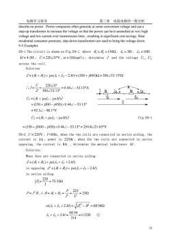
电路学习指导 第三章电阻电路的一般分析 absorbs no power.power companies often generate at some convenient voltage and use a step-up transformer to increase the voltage so that the power can be tr-ansmitted at very high voltage and low current over transmission lines,resulting in significant cost savings.Near residential consumer premises,step-down transformers are used to bring the voltage down. 9-5 Examples E9-1 The circuit is shown as Fig.E9-1,where R=R=1500,L=3H,2=10H M/=4.5H,U=22020V,@=100rad/s,determine and the voltage U,U across the coil. Solution Z=(+)+jo(L+L2-20=(300+j400)2=500∠53.132 .i= FZ500253139=04∠-53.13A 220∠0° U=(R+joL-joMi 02 =(150+j300-j450)×0.44∠-53.13° =93.3∠-98.1V i=(及+jo山-jo0/ Fig.E9-1 =(150+j1000-j450)×0.44∠-53.13°=250.8∠21.65V E9-2 U=220V,f=50Hz,when the two coils are connected in series aiding,the current is 3A,power is 225W,when the two coils are connected in series opposing,the current is 8A,determine the mutual inductance 4/. Solution: When they are connected in series aiding Z=(R+R)+jo(L+L2+20 in opposing Z=(R+R)+jo(+-2) in series aiding 14=20=7330 3 P=PR,∴R=R+R= -2m 0(山+2+2M=-R=68.942 4+6+2/=6894=022H0 314 23
电路学习指导 第三章 电阻电路的一般分析 23 absorbs no power . Power companies often generate at some convenient voltage and use a step-up transformer to increase the voltage so that the power can be tr-ansmitted at very high voltage and low current over transmission lines , resulting in significant cost savings. Near residential consumer premises, step-down transformers are used to bring the voltage down. 9-5 Examples E9-1 The circuit is shown as Fig.E9-1, where R1 = R2 =150Ω, L1 = 3H , L2 =10H , M = 4.5H , U̇ = 220∠0°V ,ω =100rad /s ,determine I ̇ and the voltage U1̇ , U2 ̇ across the coil. Solution Z = (R1 + R2 ) + jω(L1 + L2 − 2M ) = (300 + j400)Ω = 500∠53.13°Ω ∴ 0.44 53.13 A 500 53.13 220 0 = ∠ − ° ∠ ° ∠ ° = = Z U I ̇ ̇ U R L M I ̇ ̇ 1 = ( 1 + jω 1 − jω ) = (150 + j300 − j450)× 0.44∠ − 53.13° = 93.3∠ − 98.1°V U R L M I ̇ ̇ 2 = ( 2 + jω 2 − jω ) Fig.E9-1 = (150 + j1000 − j450)×0.44∠ − 53.13° = 250.8∠21.65°V E9-2 U = 220V ,f=50Hz, when the two coils are connected in series aiding, the current is 3A ,power is 225W ,when the two coils are connected in series opposing, the current is 8A , determine the mutual inductance M . Solution: When they are connected in series aiding Z = (R1 + R2 ) + jω(L1 + L2 + 2M ) in opposing Z′ = (R1 + R2 ) + jω(L1 + L2 − 2M ) in series aiding = = 73.33Ω 3 220 Z P I R2 = ,∴ = + = = = 25Ω 3 225 2 2 1 2 I P R R R ( + + 2 ) = − = 68.94Ω 2 2 ω L1 L2 M Z R 0.22H 314 68.94 L1 + L2 + 2M = = ①
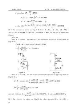
电路学习指导 第三章电阻电路的一般分析 in opposing7 (4+2-210=-R=11462 4+h-2M=1146=0.0365H@ 314 s0M:M-4+么+210=(4+4-20_02-00365-00459H 4 4 E9-3 The circuit is shown as Fig.E9-3,where R=30,R=50,@L=7.50, oL2=12.59,@M/=60,U=5020V,determine when the switch is opened and closed. Solution When S is opened,the two coils are connected in series aiding shown as Fig.E9-3a. Z=(R+及)+jo(4+L2+20=(8+j32)2 7-0-5020 28+2152∠-7596A Th8 R 13L 3jc(L+M) 3jc(L2+M) Fig.E9-3a Fig.E9-3b When s is closed,the two coils are connected in series opposing shown as Fig.E9-3b. Z=R+j(+M)+(-joMxIR+jo( =(3.99+j5.02)2 (-jo0+[R+jo(L+M] 50∠0° Z399+j502=785152A -joM current division=- ×1=3.84∠150.28A:2=1+1=11.11∠44.9°A R+jol E9-4 The circuit is shown as Fig.E9-4a,where 4=L2=IH,M/=0.5H 24
电路学习指导 第三章 电阻电路的一般分析 24 in opposing: ′ = = 27.5Ω 8 220 Z ( + − 2 ) = − =11.46Ω 2 2 ω L1 L2 M Z R 0.0365H 314 11.46 L1 + L2 − 2M = = ② so M : 0.0459H 4 0.22 0.0365 4 ( 1 2 2 ) ( 1 2 2 ) = − = + + − + − = L L M L L M M E9-3 The circuit is shown as Fig.E9-3,where R1 = 3Ω , R2 = 5Ω , ωL1 = 7.5Ω , ωL2 =12.5Ω ,ωM = 6Ω ,U̇ = 50∠0°V ,determine I ̇ when the switch is opened and closed. Solution When S is opened ,the two coils are connected in series aiding shown as Fig.E9-3a .Z = (R1 + R2 ) + jω(L1 + L2 + 2M ) = (8 + j32)Ω 1.52 75.96 A 8 32 50 0 = ∠ − ° + ∠ ° = = Z j U I ̇ ̇ Fig.E9-3a Fig.E9-3b When S is closed ,the two coils are connected in series opposing shown as Fig.E9-3b . = + Ω − + + + − × + + = + + + (3.99 j5.02) ( j ) [ j ( )] ( j ) [ j ( )] j ( ) 2 2 2 2 1 1 M R L M M R L M Z R L M ω ω ω ω ω 7.8 51.52 A 3.99 j5.02 50 0 = ∠ ° + ∠ ° = = Z U I ̇ ̇ current division 3.84 150.28 A j j 2 2 1 × = ∠ ° + − = I R L M I ̇ ̇ ω ω ; I ̇ 2 = I ̇ + I ̇ 1 =11.11∠44.9°A E9-4 The circuit is shown as Fig.E9-4a, where L1 = L2 =1H , M = 0.5H
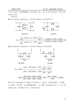
电路学习指导 第三章电阻电路的一般分析 Gi=C=lu F,=1000rad/s,determine Zir,Zi2 in Fig.9-4a and.Fig.9-4b. respectively. Solution When the mutual inductance is deleted (shown as Fig.E9-4 b) 101 02 10 M C÷ 片C2 C2 Z 1'o Fig.E9-4a Fig E9-b r.Go4+6-2n+2】 1 (-1000)×[-1000+1000] =02 1 1 loc ,(-1000)+-1000+1000 When the mutual inductance is deleted (shown as Fig.E9-4d) M C2 C C2 Fig.E9-4c Fig.E9d jo(4-Mxjo(6-2+ 1 Zi=joM+ joG joC jo(L-M0+[jo(2-20+ 0+0-0-100-j5ow+0e600-j125m =j500+j500×[j500-j100-j1001 -1000 E9-5 The transformer is shown as Fig.E9-5 a,where=R2=00,L=5H. L2=1.2H,M/=2H,=100cos(10/)V V,Z1=30,determine the of the primary and secondary part,respectively. 2
电路学习指导 第三章 电阻电路的一般分析 25 C1 = C2 =1μ F,ω =1000rad /s ,determine Z11′ , Z12 in Fig.9-4a and . Fig.9-4b, respectively. Solution When the mutual inductance is deleted (shown as Fig.E9-4 b) Fig.E9-4a Fig.E9-b = Ω − + − + − × − + = + + − + × + − + ′ = 0 ( 1000) [ 1000 1000] ( 1000) [ 1000 1000] ] j 1 [j ( 2 ) j 1 ] j 1 [j ( 2 ) j 1 2 1 2 1 2 1 2 1 11 j j j j j j C L L M C C L L M C Z ω ω ω ω ω ω When the mutual inductance is deleted (shown as Fig.E9-4d) Fig.E9-4c Fig.E9d ] j 1 j 1 j ( ) [j ( 2 ) ] j 1 j 1 j ( ) [j ( 2 ) j 1 2 1 2 1 2 1 2 12 C C L M L M C C L M L M Z M ω ω ω ω ω ω ω ω ω − + − + + − × − + + = + = Ω − × − = + + − − × − − = + j1250 1000 500 ( j1500) j500 j500 [j500 j1000 j1000] j500 [j500 j1000 j1000] j500 E9-5 The transformer is shown as Fig.E9-5 a, where R1 = R2 = 0Ω , L1 = 5H , L2 =1.2H , M = 2H , u1 =100cos(10t)V V, Z L = 3Ω , determine the i1,i2 of the primary and secondary part , respectively

电路学习指导 第三章电阻电路的一般分析 12 7 Fig.E9-5a Fig.E9-5b Fig.E9-5c Solution the equivalent circuit of primary part shown as Fig.E9-5b Z1=R+joL=j502,Z2=3+j122 .=202 若3并2=3234z-76m=(784-3137n 6-胃N 100/5 1=Z+Z50+73917350-672A the equivalent circuit of secondary part shown as Fig.E9-5c 如=学么=琴 -ioc 1 ∴1=3.50W√2c0s101-67.2)A,h=5.66√2c0s101-126.8)A E9-6 The ideal transformer shown as Fig.E9-6 a,the ratio of the turns is 1:10, us =10cos(10/)V,R=1,R=1002,calculate i2. 巴↓110 2 Fig.E9-6 a Fig.E9-6 b 26
电路学习指导 第三章 电阻电路的一般分析 26 Fig.E9-5a Fig.E9-5b Fig.E9-5c Solution the equivalent circuit of primary part shown as Fig.E9-5b Z11 = R1 + jωL1 = j50Ω , Z22 = 3 + j12Ω = ∠ − °Ω = − Ω + = = 32.34 76 (7.84 31.37) 3 j12 20 2 22 2 M 1r Z X Z 0 V 2 100 U1 = ∠ ° ̇ 3.50 67.2 A j50 7.84 j31.37 100 2 11 1r 1 1 = ∠ − ° + − = + = Z Z U I ̇ ̇ the equivalent circuit of secondary part shown as Fig.E9-5c 1 11 M OC U Z Z U̇ = ̇ , 11 2 M eq Z X Z = ∴ 5.66 126.8 A 1 22 eq 1 11 M 22 eq OC 2 = ∠ − ° + − = + − = Z Z U Z Z Z Z U I ̇ ̇ ̇ ∴i1 = 3.50 2 cos(10t − 67.2°)A , i2 = 5.66 2 cos(10t −126.8°)A E9-6 The ideal transformer shown as Fig.E9-6 a, the ratio of the turns is 1:10 , uS =10cos(10t)V , R1 =1Ω , R2 =100Ω , calculate u2 . Fig.E9-6 a Fig.E9-6 b
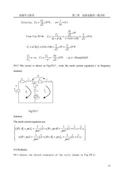
电路学习指导 第三章电阻电路的一般分析 Soulo么-设4v,”古=ol 10∠0° 2 r00Fig.E9-601=B+尾1+001x100F万<0A 会么=么名4wv-00N 50 E9-7 The circuit is shown as Fig E9-7,write the mesh current equations in frequency domain). Fig.E9-7 Solution The mesh current equations are (R+R++ i-R-w 1h=is-is c)h-in 1、 R-@L+0乙-(R+R+@人 9-6Problems P9-1 Denote the dotted terminals of the coils (shown in Fig.P9-1) 27
电路学习指导 第三章 电阻电路的一般分析 27 Solution: 0 V 2 10 US = ∠ ° ̇ , 0.1 10 1 n = = From Fig.E9-6b 0 A 2 5 1 0.01 100 0 2 10 2 2 1 S 1 = ∠ ° + × ∠ ° = + = R n R U I ̇ ̇ 0 V 2 5 0 2 5 2 1 0.01 100 2 U1 = n R I = × × ∠ ° = ∠ ° ̇ ̇ n U U = − 2 1 ̇ ̇ , 0 V 2 1 50 2 = − ∠ ° − = n U U ̇ ̇ , u2 = −50cos(10t)V E9-7 The circuit is shown as Fig.E9-7 , write the mesh current equations ( in frequency domain). U s 1 L 2 L 1 C R 2 R U s 2 R 1 I 1 I 2 M Fig.E9-7 Solution The mesh current equations are 1 2 1 2 1 1 1 2 2 2 2 1 1 ( ) ( ) 1 1 ( ) ( ) S S S R R j L I R j M I U U j C j C R j L I R R j L I U j C j C ω ω ω ω ω ω ω ω • • • • • • • ⎧ ⎫ + + + − − + = − ⎪ ⎪ ⎪ ⎪ ⎨ ⎬ ⎪ ⎪ − − + − + + + = ⎪ ⎪ ⎩ ⎭ 9-6 Problems P9-1 Denote the dotted terminals of the coils (shown in Fig.P9-1)

电路学习指导 第三章电阻电路的一般分析 Fig.P9-1a Fig.P9-1b P9-2 The circuit is shown as Fig.P9-2,=6H,L2=3H,M/=4H,determine the equivalent inductor looking from 1-1'. .1 10 1.2 1'o Fig.P9-2 a Fig.P9-2 b Fig.P9-2 c P9-3 The circuit is shown as Fig.P9-3,determine the input impedance Zn(o=radls) 10 1H 2H1 33H 'o 1'0 Fig.P9-3 a Fig.P9-3 b Fig.P9-3 c P9-4 The circuit is shown as Fig.P9-4,determine the equivalent circuit delet the mutual inductance) 20 1.10n -j4 -02 一2 6H3 34H 02' I'o Fig.P9-4 a Fig.P9-4 b P9-5 The circuit is shown as Fig.P9-5,determine the input impedance when S is opened and closed. 28
电路学习指导 第三章 电阻电路的一般分析 28 Fig.P9-1a Fig.P9-1b P9-2 The circuit is shown as Fig.P9-2 , L1 = 6H , L2 = 3H , M = 4H ,determine the equivalent inductor looking from 1-1’. Fig.P9-2 a Fig.P9-2 b Fig.P9-2 c P9-3 The circuit is shown as Fig.P9-3 , determine the input impedance Zin (ω =1rad /s ). Fig.P9-3 a Fig.P9-3 b Fig.P9-3 c P9-4 The circuit is shown as Fig.P9-4 , determine the equivalent circuit ( delet the mutual inductance) Fig.P9-4 a Fig.P9-4 b P9-5 The circuit is shown as Fig.P9-5 , determine the input impedance when S is opened and closed
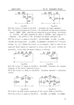
电路学习指导 第三章电阻电路的一般分析 1.10mj30n 1.1j10n j2003i20n」 60 3j12n÷-j60 10m 1'o Fig.P9-5 Fig.P9-6 P9-6 The circuit is shown as Fig.P9-6,determine the input impedance. P9-7 Two coils are connected in series,the sinusoidal voltage source acrossed them is 50HZ,220V,when they are connected in series aiding,the current is /=2.7A,the power absorbed by them is 218.7W when connected in opposing,the current is 7A,determine the mutual inductance M. P9-8 The circuit is shown as Fig.P9-8,R=R=100Q,=3H,L2=10H, M/=5H,the voltage source U=220V,@=100rad/s,determine (1)/,the coils voltage⑦,:(2)when the circuit is in resonance,what is value of the capacitor which should be connected in series with the coils.(3)draw the equivalent circuit when the mutual inductor is deleted. 。B0 M岁 10004F 6 Fig.P9-8 Fig.P9-9 P9-9 The circuit is shown as Fig.P9-9. M/=0.04H,determine the resonant frequency of the series connected circuit. P9-10 The circuit is shown as Fig.P9-10,determine Thevenin's equivalent circuit. -j5m- Fig.P9-10 Fig.P9-11 P9-11 Write the mesh current equations of the circuit shown as Fig.P9-11. P9-12 The circuit is shown as Fig.P9-12, R=502,=70mH,2=25mH 29
电路学习指导 第三章 电阻电路的一般分析 29 Fig.P9-5 Fig.P9-6 P9-6 The circuit is shown as Fig.P9-6 , determine the input impedance. P9-7 Two coils are connected in series , the sinusoidal voltage source acrossed them is 50HZ, 220V ,when they are connected in series aiding , the current is I = 2.7A ,the power absorbed by them is 218.7W ;when connected in opposing , the current is 7A ,determine the mutual inductance M . P9-8 The circuit is shown as Fig.P9-8 , R1 = R2 =100Ω , L1 = 3H , L2 =10H , M = 5H ,the voltage source U = 220V ,ω =100rad /s , determine (1) I ̇ ,the coils voltage U1̇ ,U2 ̇ ;(2)when the circuit is in resonance , what is value of the capacitor which should be connected in series with the coils. (3)draw the equivalent circuit when the mutual inductor is deleted. Fig.P9-8 Fig.P9-9 P9-9 The circuit is shown as Fig.P9-9, M = 0.04H , determine the resonant frequency of the series connected circuit.。 P9-10 The circuit is shown as Fig.P9-10, determine Thevenin’s equivalent circuit. Fig.P9-10 Fig.P9-11 P9-11 Write the mesh current equations of the circuit shown as Fig.P9-11. P9-12 The circuit is shown as Fig.P9-12,, R1 = 50Ω, L1 = 70mH , L2 = 25mH
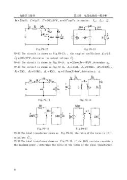
电路学习指导 第三章电阻电路的一般分析 M/=25mH,C=lu F,U=50020V,@=10'radls,determine,h2,/c Us Fig.P9-12 Fig.P9-13 P9-13 The circuit is shown as Fig.P9-13,the coupled coefficient =0.5, is=20020V,determine the output voltage 2. P9-14 The circuit is shown as Fig.P9-14,=20cos(5/+45)V,determine P9-15 The circuit is shown as Fig.P9-15,L=3.6H,L=0.06H,M/=0.465H =202,及=0.082,=-422,s=115cos(314)V,determine,. 一M L2 RL Fig.P9-14 Fig.P9-15 10 50n 101 -1 50 s① 10m Fig.P9-16 Fig.P9-17 P9-16 The ideal transformer shown as Fig.P9-16,the ratio of the turns is 10:1, calculate U,. P9-17 The ideal transformer shown as Fig.P9-17,if the 109 resistor can obtain the maximum power,determine the ratio of the turns of the ideal transformer 0
电路学习指导 第三章 电阻电路的一般分析 30 M = 25mH,C =1μ F,U̇ = 500∠0°V , 10 rad /s 4 ω = ,determine, L1 I ̇ , L2 I ̇ , I C ̇ . Fig.P9-12 Fig.P9-13 P9-13 The circuit is shown as Fig.P9-13,, the coupled coefficient K = 0.5 , U̇S = 200∠0°V ,determine the output voltage U2 ̇ . P9-14 The circuit is shown as Fig.P9-14,u1 = 20cos(5t + 45°)V ,determine u2 . P9-15 The circuit is shown as Fig.P9-15, L1 = 3.6H , L2 = 0.06H , M = 0.465H , R1 = 20Ω , R2 = 0.08Ω , RL = 42Ω , uS =115cos(314t)V ,determine i1 ,i2 . Fig.P9-14 Fig.P9-15 Fig.P9-16 Fig.P9-17 P9-16 The ideal transformer shown as Fig.P9-16, the ratio of the turns is 10 :1, calculate U 2 ̇ . P9-17 The ideal transformer shown as Fig.P9-17, if the 10Ω resistor can obtain the maximum power , determine the ratio of the turns of the ideal transformer
按次数下载不扣除下载券;
注册用户24小时内重复下载只扣除一次;
顺序:VIP每日次数-->可用次数-->下载券;
- 《电路》课程参考书籍(ELCTRIC CIRCUIT)CAPTER 8 THREE PHASE CIRCUIT.pdf
- 《电路》课程参考书籍(ELCTRIC CIRCUIT)CAPTER 7 SINUSOIDAL STEADY-STATE ANALYSIS.pdf
- 《电路》课程参考书籍(ELCTRIC CIRCUIT)CAPTER 6 SINUSOIDSAND PHASORS.pdf
- 《电路》课程参考书籍(ELCTRIC CIRCUIT)CAPTER5 OPERATIONALAMPLIFIER.pdf
- 《电路》课程参考书籍(ELCTRIC CIRCUIT)CAPTER4 CIRCUIT THEOREMS.pdf
- 《电路》课程参考书籍(ELCTRIC CIRCUIT)CAPTER3 THE SYSTEM ANALYSIS OF RESISTANCE CIRCUIT.pdf
- 《电路》课程参考书籍(ELCTRIC CIRCUIT)CHAPTER1 THE CIRCUIT ELEMENTS AND FUNDAMENTAL LAWS、CHAPTER 2 EQUIVALENT CIRCUIT OF RESISTOR CIRCUIT.pdf
- 新疆大学:《电路》课程教学大纲(自动化专业,汉).doc
- 新疆大学:《电路》课程教学大纲(电气专业,汉).doc
- 新疆大学:《电力系统分析》课程教学课件(暂态部分)第三章 电力系统三相短路电流的实用计算.pdf
- 新疆大学:《电力系统分析》课程教学课件(暂态部分)第二章 同步发电机突然三相短路分析.pdf
- 新疆大学:《电力系统分析》课程教学课件(暂态部分)第一章 电力系统故障分析的基本知识.pdf
- 新疆大学:《电力系统分析》课程教学课件(稳态部分)第六章 电力系统无功功率和电压调整.pdf
- 新疆大学:《电力系统分析》课程教学课件(稳态部分)第五章 电力系统有功功率与频率的调整.pdf
- 新疆大学:《电力系统分析》课程教学课件(稳态部分)第四章 复杂电力系统潮流的计算机算法.pdf
- 新疆大学:《电力系统分析》课程教学课件(稳态部分)第三章 简单电力网络的计算和分析.pdf
- 新疆大学:《电力系统分析》课程教学课件(稳态部分)第二章 电力系统元件模型和参数计算.pdf
- 新疆大学:《电力系统分析》课程教学课件(稳态部分)第一章 电力系统的基本概念.pdf
- 《电力系统分析》课程教学资源(学习资料)常见变压器参数(常见T参数).doc
- 《电力系统分析》课程教学资源(学习资料)常用线路参数(常见L参数).doc
- 《电路》课程参考书籍(ELCTRIC CIRCUIT)CAPTER 10 Non-sinusoidal excited circuit analysis.pdf
- 《电路》课程学习指导(含题解,d220d25ec3d145f995e5a52aaa4cab20)第一章 电路的基本概念和基本定律.doc
- 《电路》课程学习指导(含题解,d220d25ec3d145f995e5a52aaa4cab20)第二章 电阻电路的等效变换.doc
- 《电路》课程学习指导(含题解,d220d25ec3d145f995e5a52aaa4cab20)第七章 相量法.doc
- 《电路》课程学习指导(含题解,d220d25ec3d145f995e5a52aaa4cab20)第三章 电阻电路的一般分析.doc
- 《电路》课程学习指导(含题解,d220d25ec3d145f995e5a52aaa4cab20)第九章 含有耦合电感的电路.doc
- 《电路》课程学习指导(含题解,d220d25ec3d145f995e5a52aaa4cab20)第五章 含有运算放大器的电阻电路.doc
- 《电路》课程学习指导(含题解,d220d25ec3d145f995e5a52aaa4cab20)第八章 正弦稳态电路的分析.doc
- 《电路》课程学习指导(含题解,d220d25ec3d145f995e5a52aaa4cab20)第十一章 非正弦周期电流电路.doc
- 《电路》课程学习指导(含题解,d220d25ec3d145f995e5a52aaa4cab20)第十二章 二端口网络.doc
- 《电路》课程学习指导(含题解,d220d25ec3d145f995e5a52aaa4cab20)第十章 三相电路.doc
- 《电路》课程学习指导(含题解,d220d25ec3d145f995e5a52aaa4cab20)第四章 电路定理.doc
- 《电路》课程学习指导(含题解,d220d25ec3d145f995e5a52aaa4cab20)第六章 非线性电阻电路.doc
- 《电路》课程学习指导(含题解,d220d25ec3d145f995e5a52aaa4cab20)第十七章 电路方程的矩阵形式.doc
- 《电路》课程学习指导(含题解,d220d25ec3d145f995e5a52aaa4cab20)第十三章 一阶电路.doc
- 《电路》课程学习指导(含题解,d220d25ec3d145f995e5a52aaa4cab20)第十五章 动态电路的复频域求解.doc
- 《电路》课程学习指导(含题解,d220d25ec3d145f995e5a52aaa4cab20)第十八章 均匀传输线.doc
- 《电路》课程学习指导(含题解,d220d25ec3d145f995e5a52aaa4cab20)第十六章 网络函数.doc
- 《电路》课程学习指导(含题解,d220d25ec3d145f995e5a52aaa4cab20)第十四章 二阶电路.doc
- 南阳师范学院:《电子电路CAD技术》课程电子教案(PPT课件)第一章 概论.ppt
