《机器维修工程学》课程授课教案(英文)Motorcycle Carburetor Theory 101
Motorcycle Carburetor Theory 1olMotorcycle carburetors look very complex, but with a little theory, you can tuneyour bike for maximum performance. All carburetors work under the basic principleof atmospheric pressure. Atmospheric pressure is a powerful force which exertspressure on everything. It varies slightlybut is generally considered to be 15 poundsper square inch (PsI). This means that atmospheric pressure is pressing on everythingatl5PsI.Byvarying theatmospheric pressureinsidethe engine andcarburetor,wecan change the pressure and make fuel and air flow.Atmospheric pressure will force high pressure to low pressure. As the piston ona two stroke engine goes up (or goes down on a four stroke engine), a low pressureis formedinside the crankcase (above the piston on afour stroke).This low pressurealso causes a lowpressure inside the carburetor. Since the pressure is higher outsidethe engine and carburetor, air will rush inside the carburetor and engine until thepressure is equalized. The moving air going through the carburetor will pick up fuelandmixwiththeair.Inside a carburetor is a venturi, fig l.The venturi is a restriction inside thecarburetor that forces air to speed up to get through. A river that suddenly narrowscan be used to illustrate what happens inside a carb. The water in the river speedsup as it gets near the narrowed shores and will get faster if the river narrows evenmore. The same thing happens inside the carburetor. The air that is speeding up willcause atmospheric pressure to drop inside the carburetor. The faster the air moves,the lower the pressure inside the carburetor.AirVenturiSizeFlowHigh PressureFuelSupplyFIG 1Most motorcycle carburetor circuits are governed by throttle position and notby engine speed.There arefivemain metering systemsinside most motorcyclecarburetors.These metering circuits overlap each other and they are:
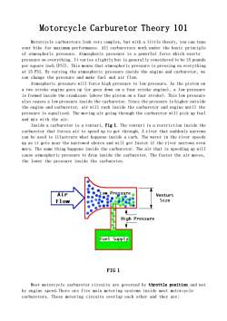
Motorcycle Carburetor Theory 101 Motorcycle carburetors look very complex, but with a little theory, you can tune your bike for maximum performance. All carburetors work under the basic principle of atmospheric pressure. Atmospheric pressure is a powerful force which exerts pressure on everything. It varies slightly but is generally considered to be 15 pounds per square inch (PSI). This means that atmospheric pressure is pressing on everything at 15 PSI. By varying the atmospheric pressure inside the engine and carburetor, we can change the pressure and make fuel and air flow. Atmospheric pressure will force high pressure to low pressure. As the piston on a two stroke engine goes up (or goes down on a four stroke engine), a low pressure is formed inside the crankcase (above the piston on a four stroke). This low pressure also causes a low pressure inside the carburetor. Since the pressure is higher outside the engine and carburetor, air will rush inside the carburetor and engine until the pressure is equalized. The moving air going through the carburetor will pick up fuel and mix with the air. Inside a carburetor is a venturi, fig 1. The venturi is a restriction inside the carburetor that forces air to speed up to get through. A river that suddenly narrows can be used to illustrate what happens inside a carb. The water in the river speeds up as it gets near the narrowed shores and will get faster if the river narrows even more. The same thing happens inside the carburetor. The air that is speeding up will cause atmospheric pressure to drop inside the carburetor. The faster the air moves, the lower the pressure inside the carburetor. FIG 1 Most motorcycle carburetor circuits are governed by throttle position and not by engine speed.There are five main metering systems inside most motorcycle carburetors. These metering circuits overlap each other and they are:
* pilot circuit*throttlevalve* needle jet and jet needle*main jet*choke circuitThe pilot circuit has two adjustable parts, fig 2. The pilot air screw and pilotjet. The air screw can be located either near the back side of the carburetor or nearthe front of the carburetor.If the screw is located near the back,it regulates howmuch air enters the circuit. If the screwis turned in, it reduces the amount of airand richens the mixture. If it is turned out, it opens the passage more and allowsmore air into the circuit which results in a lean mixture.If the screw is locatednearthefront,it regulated fuelThe mixture will be leaner ifit isscrewed inand richer if screwed out.If theair screwhastobeturned morethan2turnsoutfor best idling,the next smaller size pilot jet will be needed.Air FlowFuelSupplyFIG 2Thepilot jetis the part which supplies most of thefuel at lowthrottle openings.Ithasasmallholeinitwhichrestrictsfuelflowthoughit.Boththepilotairscrew and pilot jet affects carburetion from idle to around 1/4 throttle.The slide valve affects carburetion between 1/8 thru 1/2 throttle. It especiallyaffects it between 1/8 and 1/4 and has a lesser affect up to 1/2. The slides comeinvarioussizesand the size isdetermined byhowmuch is cutawayfrom thebacksideof it,fig3.Thelargerthe cutaway,theleanerthemixture(sincemoreairisallowedthrough it) and the smaller the cutaway,the richer the mixture will be. Throttle
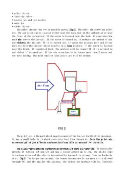
* pilot circuit * throttle valve * needle jet and jet needle * main jet * choke circuit The pilot circuit has two adjustable parts, fig 2. The pilot air screw and pilot jet. The air screw can be located either near the back side of the carburetor or near the front of the carburetor. If the screw is located near the back, it regulates how much air enters the circuit. If the screw is turned in, it reduces the amount of air and richens the mixture. If it is turned out, it opens the passage more and allows more air into the circuit which results in a lean mixture. If the screw is located near the front, it regulated fuel. The mixture will be leaner if it is screwed in and richer if screwed out. If the air screw has to be turned more than 2 turns out for best idling, the next smaller size pilot jet will be needed. FIG 2 The pilot jet is the part which supplies most of the fuel at low throttle openings. It has a small hole in it which restricts fuel flow though it. Both the pilot air screw and pilot jet affects carburetion from idle to around 1/4 throttle. The slide valve affects carburetion between 1/8 thru 1/2 throttle. It especially affects it between 1/8 and 1/4 and has a lesser affect up to 1/2. The slides come in various sizes and the size is determined by how much is cutaway from the backside of it, fig 3. The larger the cutaway, the leaner the mixture (since more air is allowed through it) and the smaller the cutaway, the richer the mixture will be. Throttle

valves have numbers on them that explains howmuch the cutaway is.If there is a 3stamped into the slide,it has a 3.Omm cutaway, while a l will have a l.Omm cutaway(which will bericher than a3).ThrottleslideValveCutawayhigher=leanerFIG3The jet needle and needle jet affects carburetion from 1/4 thru 3/4 throttle.The jet needle is a long tapered rod that controls how much fuel can be drawn intothe carburetor venturi.The thinner the taper, the richer the mixture. The thickerthe taper,theleaner themixturesince thethicker taperwill not allowasmuchfuelinto the venturi as a leaner one.The tapers are designed very precisely to givedifferentmixtures at different throttle openings.Jet needles have grooves cut intothe top. A clip goes into one of these grooves and holds it from falling or movingfrom the slide. The clip position can be changed to make an engine run richer or leaner,fig4.If theengineneeds torunleaner,theclip wouldbemovedhigher.This willdrop the needlefarther down intothe needlejet and cause lessfuelto flowpastit.If theclip islowered,the jet needle is raised and themixturewill bericher.Theneedle jet is wherethe jet needle slides into.Depending on the inside diameterof theneedle jet,itwill affect the jet needle.The needle jetand jetneedleworktogether to control the fuel flow between the1/8 thru 3/4range. Most of the tuningfor this range is done to the jet needle, and not the needle jet
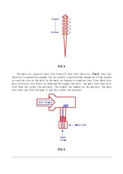
valves have numbers on them that explains how much the cutaway is. If there is a 3 stamped into the slide, it has a 3.0mm cutaway, while a 1 will have a 1.0mm cutaway (which will be richer than a 3). FIG 3 The jet needle and needle jet affects carburetion from 1/4 thru 3/4 throttle. The jet needle is a long tapered rod that controls how much fuel can be drawn into the carburetor venturi. The thinner the taper, the richer the mixture. The thicker the taper, the leaner the mixture since the thicker taper will not allow as much fuel into the venturi as a leaner one. The tapers are designed very precisely to give different mixtures at different throttle openings. Jet needles have grooves cut into the top. A clip goes into one of these grooves and holds it from falling or moving from the slide. The clip position can be changed to make an engine run richer or leaner, fig 4. If the engine needs to run leaner, the clip would be moved higher. This will drop the needle farther down into the needle jet and cause less fuel to flow past it. If the clip is lowered, the jet needle is raised and the mixture will be richer. The needle jet is where the jet needle slides into. Depending on the inside diameter of the needle jet, it will affect the jet needle. The needle jet and jet needle work together to control the fuel flow between the 1/8 thru 3/4 range. Most of the tuning for this range is done to the jet needle, and not the needle jet
LeanerRicherFIG 4Themainjet controlsfuelflowfrom3/4thrufullthrottle,fig5.Oncethethrottle is opened far enough,the jet needleis pulledhigh enough out of the needlejet and the size of the hole in the main jet begins to regulate fuel flow.Main jetshave different size holes in them and the bigger the hole, the more fuel that willflow (and the richer the mixture).Thehigher the number on the mainjet,the morefuel that can flow through it and the richer the mixture.AirFlowMainJet01-FuelFlowFIG5
FIG 4 The main jet controls fuel flow from 3/4 thru full throttle, fig 5. Once the throttle is opened far enough, the jet needle is pulled high enough out of the needle jet and the size of the hole in the main jet begins to regulate fuel flow. Main jets have different size holes in them and the bigger the hole, the more fuel that will flow (and the richer the mixture). The higher the number on the mainjet, the more fuel that can flow through it and the richer the mixture. FIG 5
The choke system is used tostart cold engines.Sincethefuel in a cold engineis sticking to the cylinder walls due to condensation, the mixture is too lean forthe engine to start. The choke system will add fuel to the engine to compensate forthe fuel that is stuck to the cylinder walls. Once the engine is warmed up,condensationisnotaproblem,andthechokeisnotneeded.Theair/fuelmixturemustbechanges tomeet thedemandsof theneedsof theengine.The ideal air/fuel ratiois l4.7 grams of air to l gram of fuel. This ideal ratiois only achieved for a very short period while the engine is running.Due to theincomplete vaporization of fuel at slow speeds or the additional fuel required athigh speeds, the actual operational air/fuel ratio is usually richer.Figure6 showsthe actual air/fuel ratio for any given throttle opening.Lean18:116:114.7:114:1Air/Fuel12: 1Ratio10:18:16: 1Rich·FullStartIdleCruiseThrottleFIG 6Carburetor Jetting TroubleshootingCarburetor troubleshooting is simple once the basic principles are known.Thefirst step is to find where the engine is running poorly, fig 7.It must be rememberedthatcarburetor jettingisdetermined bythe throttleposition,not enginespeedIftheengineishavingtroublesatlowrpm(idletol/4throttle),thepilotsystemorslidevalveisthelikelyproblem.Iftheenginehasproblemsbetween1/4and3/4throttle,the jet needle and needlejet (most likelythe jet needle) islikelytheproblem. If the engine is running poorly at 3/4 to full throttle, the main jet isthe likely problem
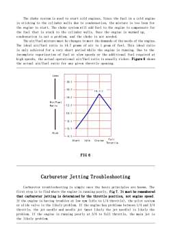
The choke system is used to start cold engines. Since the fuel in a cold engine is sticking to the cylinder walls due to condensation, the mixture is too lean for the engine to start. The choke system will add fuel to the engine to compensate for the fuel that is stuck to the cylinder walls. Once the engine is warmed up, condensation is not a problem, and the choke is not needed. The air/fuel mixture must be changes to meet the demands of the needs of the engine. The ideal air/fuel ratio is 14.7 grams of air to 1 gram of fuel. This ideal ratio is only achieved for a very short period while the engine is running. Due to the incomplete vaporization of fuel at slow speeds or the additional fuel required at high speeds, the actual operational air/fuel ratio is usually richer. Figure 6 shows the actual air/fuel ratio for any given throttle opening. FIG 6 Carburetor Jetting Troubleshooting Carburetor troubleshooting is simple once the basic principles are known. The first step is to find where the engine is running poorly, fig 7. It must be remembered that carburetor jetting is determined by the throttle position, not engine speed. If the engine is having troubles at low rpm (idle to 1/4 throttle), the pilot system or slide valve is the likely problem. If the engine has problems between 1/4 and 3/4 throttle, the jet needle and needle jet (most likely the jet needle) is likely the problem. If the engine is running poorly at 3/4 to full throttle, the main jet is the likely problem
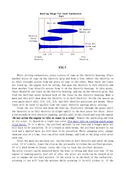
Horking Range For Each CarburetorPartMain JetJet NeedlelNeedle JetThrottleValveCutawayPilot AirScrew andJet1/23/41/81/4FullClosedThrottleThrottleFIG 7While jetting carburetors, place a piece of tape on the throttle housing. Placeanother piece of tape on the throttlegripand draw a line(whilethethrottle isat idle) straight across from one piece of tape to the other. When these two linesare lined up,the engine will be idling. Now open the throttle to full throttle anddraw another line directly across from it on the throttle housing. At this point,there should be two lines on the throttle housing, and one on the throttle grip. Nowfind the half-way point between both of thelines on the throttle housing.Make amark and this will show when the throttle is at half throttle. Divide the spaces upevenagainuntilidle,1/4,1/2andfull throttlepositionsareknown.These3/4lines willbeused to.throttle opening while jetting.ouicklyindClean the air filterelerate through thegearsuntilthethrottle is at fullthe best place for this). Afterthro+afewsecondsof full throttlequicklypull in theclutchandstoptheenginerunnin(Do not allow the engine to idle or Remove the spark plug and lookto a stop)coastat its color.It should bealightcolor(for more info onreading sparkplugs+aclick here). If it's white,the air/fuelmixtureis toolean and a biggermain jetwillhave tobe installed.Ifit'sblackordarkbrown,the air/fuel mixtureistoorich and a smaller main jet will have to be installed. while changing jets, changethem one size at a time, test run aftereach change, and look at the plug color aftereach run.After the main jet has been set,run the bike at half throttle and check the plugcolor. If it's white, lower the clip on the jet needle torichen the air/fuel mixture.If it's dark brown orblack, raise the clip to lean the air/fuel mixture.The pilot circuit can be adjusted while the bike is idling and then test run. If theengine is running poorly just off of idle, the pilot jet screw can be turned in orout to change the air-fuel mixture. If the screw is in the back of the carburetor,screwing it out will lean the mixture while screwing it in will richen it. If the
FIG 7 While jetting carburetors, place a piece of tape on the throttle housing. Place another piece of tape on the throttle grip and draw a line (while the throttle is at idle) straight across from one piece of tape to the other. When these two lines are lined up, the engine will be idling. Now open the throttle to full throttle and draw another line directly across from it on the throttle housing. At this point, there should be two lines on the throttle housing, and one on the throttle grip. Now find the half-way point between both of the lines on the throttle housing. Make a mark and this will show when the throttle is at half throttle. Divide the spaces up even again until idle, 1/4, 1/2, 3/4, and full throttle positions are known. These lines will be used to quickly find the exact throttle opening while jetting. Clean the air filter and warm the bike up. Accelerate through the gears until the throttle is at full throttle (a slight uphill is the best place for this). After a few seconds of full throttle running, quickly pull in the clutch and stop the engine (Do not allow the engine to idle or coast to a stop). Remove the spark plug and look at its color. It should be a light tan color (for more info on reading spark plugs click here). If it's white, the air/fuel mixture is too lean and a bigger main jet will have to be installed. If it's black or dark brown, the air/fuel mixture is too rich and a smaller main jet will have to be installed. While changing jets, change them one size at a time, test run after each change, and look at the plug color after each run. After the main jet has been set, run the bike at half throttle and check the plug color. If it's white, lower the clip on the jet needle to richen the air/fuel mixture. If it's dark brown or black, raise the clip to lean the air/fuel mixture. The pilot circuit can be adjusted while the bike is idling and then test run. If the engine is running poorly just off of idle, the pilot jet screw can be turned in or out to change the air-fuel mixture. If the screw is in the back of the carburetor, screwing it out will lean the mixture while screwing it in will richen it. If the
adjustment screwis in the front of the carburetor, it will be the opposite. If turningthe screw between one and two and a half doesn't have any affect, the pilot jet willhave to be replaced with either a larger or smaller one. While adjusting the pilotscrew, turn it 1/4 turn at a time and test run the bike between adjustments.Adjustthepilot circuit until themotorcyclerunscleanlyoff of idlewithno hesitationsorbogs.Altitude, Humidy, and Air TemperatureOnce the jetting is set and the bike is running good, there are many factors thatwill change the performane of the engine.Altitude,air temperature,and humidityare big factors that will affect howan engine will run.Air density increases asair gets colder. This means that there are more oxygen molecules in the same spacewhen the air is cold. When the temerature drops, the engine will run leaner and morefule will have to be added to compensate. When the air temerature gets warmer, theengine will run richer and less fuel will be needed. An engine that is jetted at 32sfahrenheight mayrun poorlywhen thetemperature reaches 9os fahrenheightAltitude affects jetting since there are less air molecules as altitude increases.A bike that runs good at sea level will run rich at lo,ooo ft due to the thinner air.Humidyishowmuchmoisteris intheair.As humidyincreases,jettingwillbericher.A bike that runs fins in the mornings dry air may run rich as the day goes on andthehumidityincreases.Correction factors are sometimes used to find the correct carburetor settingsfor changing temperatures and altitudes. The chart in fig 8, shows a typicalcorrection factor chart. To use this chart, jet the carburetor and write down thepilot and main jet sizes. Determine the correct air temperature and follow the chartover to the right until the correct elevation is found. Move straight down from thispoint until the correct coreection factor is found. Using fig 8 as an example, theairtemperature is95sfahrenheight andthealtitudeis3200ft.Thecorrectionfactorwillbe O.92.Tofind out the correction main andpilot jets, multiplethe correctionfactor and each jet size.A main jet size of 350 would be multiplied by 0.92 and thenew main jet size would be a 322. A pilot jet size of 40 would be multiplied by 0.92andthepilotjetsizewouldbe36.8
adjustment screw is in the front of the carburetor, it will be the opposite. If turning the screw between one and two and a half doesn't have any affect, the pilot jet will have to be replaced with either a larger or smaller one. While adjusting the pilot screw, turn it 1/4 turn at a time and test run the bike between adjustments. Adjust the pilot circuit until the motorcycle runs cleanly off of idle with no hesitations or bogs. Altitude, Humidy, and Air Temperature Once the jetting is set and the bike is running good, there are many factors that will change the performane of the engine. Altitude, air temperature, and humidity are big factors that will affect how an engine will run. Air density increases as air gets colder. This means that there are more oxygen molecules in the same space when the air is cold. When the temerature drops, the engine will run leaner and more fule will have to be added to compensate. When the air temerature gets warmer, the engine will run richer and less fuel will be needed. An engine that is jetted at 32š fahrenheight may run poorly when the temperature reaches 90š fahrenheight. Altitude affects jetting since there are less air molecules as altitude increases. A bike that runs good at sea level will run rich at 10,000 ft due to the thinner air. Humidy is how much moister is in the air. As humidy increases, jetting will be richer. A bike that runs fins in the mornings dry air may run rich as the day goes on and the humidity increases. Correction factors are sometimes used to find the correct carburetor settings for changing temperatures and altitudes. The chart in fig 8, shows a typical correction factor chart. To use this chart, jet the carburetor and write down the pilot and main jet sizes. Determine the correct air temperature and follow the chart over to the right until the correct elevation is found. Move straight down from this point until the correct coreection factor is found. Using fig 8 as an example, the air temperature is 95š fahrenheight and the altitude is 3200 ft. The correction factor will be 0.92. To find out the correction main and pilot jets, multiple the correction factor and each jet size. A main jet size of 350 would be multiplied by 0.92 and the new main jet size would be a 322. A pilot jet size of 40 would be multiplied by 0.92 and the pilot jet size would be 36.8
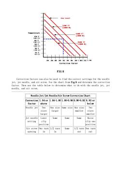
Sea Level3208FT(1988#)Tenperature6488FT(2008)104F(40 C)86 F968FT(30 C)(3888N)68F(20 C)50F(10C)32F(0 C).84.86.88.90.92.94.96.981.001.021.04Correction FactorFIG 8Correction factors can also be used to find the correct settings for the needlejet, jet needle, and air screw. Use the chart from fig 9 and determin the correctionfactor. Then use the table below to determine what to do with the needle jet,jetneedle, and air screw.NeedleJet/JetNeedle/AirScrewCorrectionChartCorrection1.04or1.04-1.001.00-0.960.96-0.920.920rfactorabovebelowNeedle jetTwoTwoOne sizeSame sizeOne sizelargersmallersizessizeslargersmallerJetneedleLowerSameSameSameRaiseclipcliponesettingpositionpositionAirscrewOneturn1/2turnSame1/2 turnOneturnininoutoutopening
FIG 8 Correction factors can also be used to find the correct settings for the needle jet, jet needle, and air screw. Use the chart from fig 9 and determin the correction factor. Then use the table below to determine what to do with the needle jet, jet needle, and air screw. Needle Jet/Jet Needle/Air Screw Correction Chart Correction factor 1.04 or above 1.04-1.00 1.00-0.96 0.96-0.92 0.92 or below Needle jet Two sizes larger One size larger Same size One size smaller Two sizes smaller Jet needle setting Lower clip position Same Same Same Raise clip one position Air screw opening One turn in 1/2 turn in Same 1/2 turn out One turn out
按次数下载不扣除下载券;
注册用户24小时内重复下载只扣除一次;
顺序:VIP每日次数-->可用次数-->下载券;
- 《机器维修工程学》课程授课教案(英文)How Automatic Transmissions Work.doc
- 《机器维修工程学》课程授课教案(英文)How car engine work.doc
- 《机器维修工程学》课程授课教案(英文)How does a carburetor work.doc
- 《机器维修工程学》课程授课教案(英文)How Turbochargers Work.doc
- 《机器维修工程学》课程授课教案(石河子大学:赵永满).doc
- 《机器维修工程学》课程教学大纲 Maintenance Engineering.pdf
- 《机械制造基础》课程PPT教学课件(机械工程材料)第八章 有色金属及其合金.ppt
- 《机械制造基础》课程PPT教学课件(机械工程材料)第七章 铸铁.ppt
- 《机械制造基础》课程PPT教学课件(机械工程材料)第一章 材料的性能.ppt
- 《机械制造基础》课程PPT教学课件(机械工程材料)第十一章 复合材料.ppt
- 《机械制造基础》课程PPT教学课件(机械工程材料)第十章 陶瓷材料.ppt
- 《机械制造基础》课程PPT教学课件(机械工程材料)第九章 高分子材料.ppt
- 《机械制造基础》课程PPT教学课件(机械工程材料)总复习.ppt
- 《机械制造基础》课程教学资源(复习资料)疑难问题解答(一).ppt
- 《机械制造基础》课程教学资源(复习资料)工程材料学习指导.doc
- 《机械制造基础》课程教学资源(复习资料)疑难问题解答(三).ppt
- 《机械制造基础》课程教学资源(复习资料)疑难问题解答(二).doc
- 《机械制造基础》课程教学大纲(一)Machine Manufacturing foundation(适用专业:机械设计制造及其自动化).doc
- 《机械制造基础》课程教学大纲(二)Machine Manufacturing foundation(适用专业:机械设计制造及其自动化).doc
- 《机械制造基础》课程教学大纲 Machine Manufacturing foundation(适用专业:工业工程).doc
- 《机器维修工程学》课程教学课件(讲稿)测点的设置和传感器的安装.pdf
- 《机器维修工程学》课程教学课件(讲稿)滚动轴承故障诊断 Rolling Element Bearing Diagnosis.pdf
- 《机器维修工程学》课程教学课件(讲稿)机器振动特征分析(3/3).pdf
- 《机器维修工程学》课程教学课件(讲稿)设备诊断技术的应用和发展.pdf
- 《机器维修工程学》课程教学课件(PPT讲稿)设备状态监测与故障诊断讲座.ppt
- 《机器维修工程学》课程教学课件(讲稿)机器振动特征分析(1/3).pdf
- 《机器维修工程学》课程教学课件(讲稿)机器振动特征分析(2/3).pdf
- 《机器维修工程学》课程教学课件(PPT讲稿)发动机压缩系的修理.ppt
- 《机器维修工程学》课程教学课件(PPT讲稿)设备修理和零件修复技术-2/2.ppt
- 《机器维修工程学》课程教学课件(PPT讲稿)设备修理和零件修复技术-1/2.ppt
- 《机器维修工程学》课程教学课件(PPT讲稿)修理前的准备工作.ppt
- 《机器维修工程学》课程教学课件(PPT讲稿)第一章 故障诊断学(2/3).ppt
- 《机器维修工程学》课程教学课件(PPT讲稿)第一章 故障诊断学(1/3).ppt
- 《机器维修工程学》课程教学课件(PPT讲稿)第二章 机械零件生效分析.ppt
- 《机器维修工程学》课程教学课件(PPT讲稿)第三章 产品的极限技术状态.ppt
- 《机器维修工程学》课程教学课件(PPT讲稿)第一章 故障诊断学(3/3).ppt
- 《机器维修工程学》课程教学课件(PPT讲稿)机械设备的故障及可靠性理论.ppt
- 《机器维修工程学》课程教学课件(PPT讲稿)绪论工业工程.ppt
- 《机器维修工程学》课程教学课件(PPT讲稿)绪论.ppt
- 《机械工程测试技术基础》课程教学大纲 Fundamentals of Test & Measurement Technology.doc
