同济大学:《有限元方法》课程教学资源(教案讲义)Chapter 2 Stiffness Matrices, Spring and Bar Elements

FEM-Chapter 2 Basic concepts introduced Stiffness Matrices,Spring and Bar Elements smtyodekmemm Introduction to types of elements 1-Pdlin .. 树倒 州 [例 [-份 树 1
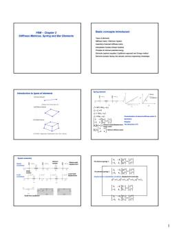
1 FEM – Chapter 2 Stiffness Matrices, Spring and Bar Elements Basic concepts introduced: Types of elements Stiffness matrix Element, System Assembly of element stiffness matrix Interpolation function (Shape function) Principle of minimum potential energy Elements (system) equation: Equilibrium approach and Energy method Element example: Spring, Bar (simple, common engineering knowledge) Introduction to types of elements k k k k k k u f f f u u k k k k f k u u f k u u f f f k k u u e e 2 1 2 1 2 2 1 1 2 1 1 2 2 1 ( ) ( ) 0 ( ) Element stiffness matrix Element nodal {displacement, force} vector Characteristics of element stiffness matrix K: Symmetry; Singular; The dimension of K Spring element System assembly Global nodal displacement Element number Nodal number Nodal force equilibrium Local nodal displacement Global coordinate Local coordinate (2) 3 (2) 2 3 2 2 2 2 2 (1) 2 (1) 1 2 1 1 1 1 1 3 (2) 2 2 (2) 2 1 (1) 1 2 (1) 1 (2) 3 (2) 2 (2) 2 (2) 1 2 2 2 2 (1) 2 (1) 1 (1) 2 (1) 1 1 1 1 1 , , , f f U U k k k k f f U U k k k k u U u U u U u U f f u u k k k k f f u u k k k k Displacement compatibility conditions (displacement continuity) For element (spring) 1: For element (spring) 2:

调 [-F 图 安网 -Rm+炉-m5 卧阁 Example aoae时 ie ayorgp wm nding to the local 3ch的at N(E)-0.N(L)- d apply boandan N2()=x/L ng:no be )=-xL4+L4 2」
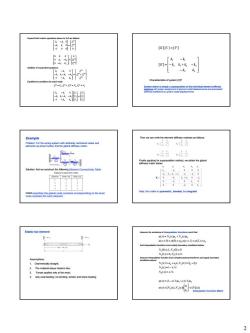
2 3 2 1 3 2 1 2 2 1 1 2 2 1 1 3 (2) 2 3 (2) 2 (1) 1 2 (1) 1 (2) 3 (2) 2 (1) 2 (1) 1 2 2 1 1 2 2 1 1 (2) 3 (2) 2 2 2 2 2 (1) 2 (1) 1 1 1 1 1 0 0 , , 0 0 0 0 0 0 0 0 0 0 0 0 0 0 F F F U U U k k k k k k k k f F f f F f F f f f f k k k k k k k k f f k k k k f f k k k k Expand both matrix equations above to 3x3 as follows: Addition of expanded equations: Equilibrium conditions for each node: 2 2 1 1 2 2 1 1 [ ] [ ]{ } [ ] k k k k k k k k K K U F Characteristics of system [K]? System matrix is simply a superposition of the individual element stiffness matrices with proper assignment of element nodal displacements and associated stiffness coefficients to system nodal displacements. Example Problem: For the spring system with arbitrarily numbered nodes and elements as shown below, find the global stiffness matrix. Solution: first we construct the following Element Connectivity Table Which specifies the global node numbers corresponding to the local node numbers for each element. Then we can write the element stiffness matrices as follows: Finally applying for superposition method, we obtain the global stiffness matrix below: Note: the matrix is symmetric, banded, but singular! Elastic bar element Assumptions: 1. Geometrically straight; 2. The material obeys Hooke’s law; 3. Forces applied only at the ends; 4. only axial loading; no bending, torsion and shear loading. ( ) [ ( ), ( )] [ ]{ } ( ) (1 / ) ( / ) ( ) / ( ) 1 / ( ) , ( ) ( ) 0, ( ) 1 (0) 1, (0) 0 ( 0) (0) ; ( ) ( ) ( ) ( ) ( ) 2 1 1 2 1 2 2 1 1 0 1 2 0 1 1 2 1 2 1 2 1 1 2 2 N u u u u x N x N x u x x L u x L u N x x L N x x L N x a a x N x b b x N L N L N N u x u u u x L u L u u x N x u N x u Assume the existence of interpolation functions such that: And interpolation functions must satisfy boundary conditions below: Assume interpolation function to be simplest polynomial forms and apply boundary conditions above: Interpolation functions Matrix

=--4=4-4 -份 子m 张的阁 卧的 So FE 非 2是-2 - ==国=-Lvz Notes: e values of the cross-sectonal areas should be 3
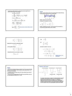
3 1 1 1 1 1 1 1 1 ( ), ( ) ( ) , , , 2 1 2 1 1 2 1 2 2 1 2 1 2 1 2 1 L AE k f f u u L AE u u L AE u u f L AE f u u L AE P A L u u E E L u u dx du L P AE k AE PL e x x x x x To determine the relation between the nodal displacements and applied forces to obtain the stiffness matrix for the bar element: Characteristics of element stiffness matrix ? Example Problem: Find the stresses in the two bar assembly which is loaded with force P, and constrained at the both ends, as shown below: Solution: using two 1D-bar elements. For element 1 and element 2, we have: Imagine a frictionless pin at node 2, which connects the two elements.we can assemble the global stiffness matrix as follows: Applying load and boundary conditions(BC) below: So FE equation becomes Deleting first and third row and column, we obtain Thus and So stresses in element 1 and 2 are: Indicating that bar 2 is in compression! Notes: • In this case the calculated stresses in elements 1 and 2 are exact as the linear theory for 1-D bar structures. It will not help if we further divide element 1 or 2 into smaller finite elements. • For tapered bars, the average values of the cross-sectional areas should be used for the elements. • We need to find the displacements first in order to find the stresses, since we are using displacement-based FEM, i.e., DSM. Fig. a depicts a tapered elastic bar subjected to an applied tensile load P at one end and attached to a fixed support at the other end. The cross-sectional area varies linearly from A0 at the fixed support at x=0 to A0/2 at x=L. Calculate the displacement of the end of the bar (a) by modeling the bar as a single element having cross-sectional area equal to the area of the actual bar at its midpoint along the length, (b) using two bar elements of equal length and similarly evaluating the area at the midpoint of each, and (c) using integration to obtain the exact solution. Application of Bar element One-element model Two-element model

= A-P )-40-a12D 6=0-西 6标6,E=0-x fe云a=lbw先 Minimum Potential Energy Distributed Load op a ne on for a bar wit tonwh8s n-nU.U.-.U,) 《-4心-+吗-, Bar Element-Formal Method n=U,-r-%-+,----4 k=∫B'EBdW =0-23 E89eageemr 2 To obtain Bfor a bar,we must first find 4
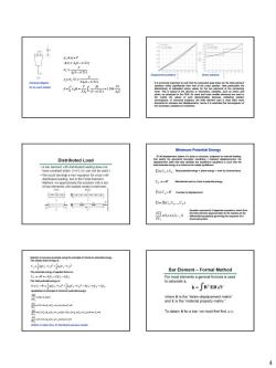
4 L L x x x x x A E PL x L dx EA P dx EA x L P E A x L P A x A x L A x P 0 0 0 0 0 0 0 1.386 (1 / 2 ) (1 / 2 ) / (1 / 2 ) ( ) (1 / 2 ) ( ) free-body diagram for an exact solution It is extremely important to note that the computed axial stress for the finite element solutions varies significantly from that of the exact solution. Note particularly the discontinuity of calculated stress values for the two elements at the connecting node. This is typical of the derived, or secondary, variables, such as stress and strain, as computed in the FEM. As more and more smaller elements are used in the model, the values of such discontinuities decease, indicating solution convergence. In structural analyses, the finite element user is most often more interested in stresses and displacements, hence it is essential that convergence of the secondary variables be monitored. Displacement solutions Stress solutions Minimum Potential Energy i N U U U U U W U W U U i N e F e F 0, 1,2,..., ( , ,..., ) 1 2 Of all displacement states of a body or structure, subjected to external loading, that satisfy the geometric boundary conditions ( imposed displacements), the displacement state that also satisfies the equilibrium equations is such that the total potential energy is a minimum for stable equilibrium. Total potential energy = strain energy + work by external force Mechanical work is a loss in potential energy Function of displacement Equation represents N algebraic equations, which form the finite element approximation to the solution of the differential equation(s) governing the response of a structural system. Solution to previous example using the principle of minimum potential energy. The elastic strain energy is: 1 1 2 2 3 3 2 2 3 2 2 1 2 1 ( ) 2 1 ( ) 2 1 Ue W k U U k U U FU F U FU The potential energy of applied forces is: UF W F1U1 F2U2 F3U3 The total potential energy is: 0, 1,2,3 i Ui 2 2 3 2 2 1 2 1 ( ) 2 1 ( ) 2 1 Ue k U U k U U Application of principle of minimum potential energy: 1/ 2 2 ( ) (1) 0 1/ 2 2 ( ) (1) 1/ 2 2 ( ) ( 1) 0 1/ 2 2 ( ) ( 1) 0 2 3 2 3 3 1 2 1 2 3 2 2 2 1 2 1 1 1 k U U F U k U U k U U F U k U U F U Written in matrix form, it’s identical to previous results

Bar Element-Formal Method Bar Element-Formal Method Let us assume that .The axial strain is given by. 2}a 6-会-[Nawe-片 .Thus e,(L. .Nis called the shape function matrix. 。A,h透 -是…别
5 Conclusions Two linear mechanical elements, the idealized elastic spring and an elastic tension compression member (bar) have been used to introduce the basic concepts involved in formulating the equations governing a finite element. The element equations are obtained by both a straightforward equilibrium approach and a strain energy method. The principle of minimum potential also is introduced
按次数下载不扣除下载券;
注册用户24小时内重复下载只扣除一次;
顺序:VIP每日次数-->可用次数-->下载券;
- 同济大学:《有限元方法》课程教学资源(教案讲义)Chapter 1 Finite Element Method - Introduction to Finite Element Method.pdf
- 同济大学:《有限元方法》课程教学资源(试卷习题)WORKSHOP 10 SUPPORT BRACKET.pdf
- 同济大学:《有限元方法》课程教学资源(试卷习题)考核试卷(A卷)2011-2012学年第1学期(含解答).pdf
- 《基础工程》课程教学资源(参考资料)中华人民共和国行业标准(JTG D63-2007)公路桥涵地基及基础设计规范(报批初稿)Code for Design of Ground Base and Foundation of Highway Bridges and Culverts.pdf
- 《基础工程》课程教学资源(参考资料)中华人民共和国行业标准(JTG D62-2004)公路钢筋混凝土及预应力混凝土桥涵设计规范 Code for Design of Highway Reinforced Concrete and Prestressed Concrete Bridges and Culverts.pdf
- 《基础工程》课程教学资源(参考资料)中华人民共和国行业标准(JTG D61-2005)公路圬工桥涵设计规范.pdf
- 《基础工程》课程PPT教学课件(英文讲稿)Chapter 09 Sheet-Pile Walls(Cantilevered and Anchored).ppt
- 《基础工程》课程PPT教学课件(英文讲稿)Chapter 08 Mechanically Stabilized Earth and Concrete Retaining Walls.ppt
- 《基础工程》课程PPT教学课件(英文讲稿)Chapter 07 Mat Foundation.ppt
- 《基础工程》课程PPT教学课件(英文讲稿)Chapter 06 Special footings and beams on the elastic foundations.ppt
- 《基础工程》课程PPT教学课件(英文讲稿)Chapter 05 Spread footing design.ppt
- 《基础工程》课程PPT教学课件(英文讲稿)Chapter 04 Factors to consider in foundation design.ppt
- 《基础工程》课程PPT教学课件(英文讲稿)Chapter 03 Improving Site Soils for Foundation Use.ppt
- 《基础工程》课程PPT教学课件(英文讲稿)Chapter 02 基础承载力 Bearing capacity of foundation(2/2).ppt
- 《基础工程》课程PPT教学课件(英文讲稿)Chapter 02 基础承载力 Bearing capacity of foundation(1/2).ppt
- 《基础工程》课程PPT教学课件(英文讲稿)Chapter 02 Bearing capacity of foundations.ppt
- 《基础工程》课程PPT教学课件(英文讲稿)Chapter 10 Single Piles(2/2).ppt
- 《基础工程》课程PPT教学课件(英文讲稿)Chapter 10 Single Piles(1/2).ppt
- 《基础工程》课程PPT教学课件(英文讲稿)Chapter 01 Introduction.ppt
- 长沙理工大学:《基础工程》课程电子教案(PPT课件)绪论(主讲:赵明华).ppt
- 同济大学:《有限元方法》课程教学资源(教案讲义)Chapter 3 Direct Stiffness Method(DSM).pdf
- 同济大学:《有限元方法》课程教学资源(教案讲义)Chapter 4 Flexure elements.pdf
- 同济大学:《有限元方法》课程教学资源(教案讲义)Chapter 6 Interpolation Functions for General Element Formulation.pdf
- 同济大学:《有限元方法》课程教学资源(教案讲义)Chapter 7 Isoparametric Element.pdf
- 同济大学:《有限元方法》课程教学资源(教案讲义)Chapter 8 Practical modeling Issues.pdf
- 北京化工大学:《过程设备设计》课程教学资源(课件讲稿)第四章 压力容器设计 Design of Pressure Vessels 4.3 常规设计 4.3.4 密封装置设计.pdf
- 上海海洋大学:工程学院2011年版课程教学大纲汇编(正文).pdf
- 上海海洋大学:食品学院2018年版课程教学大纲汇编(能源与动力、建筑环境专业).pdf
- 上海海洋大学:工程学院2018版课程教学大纲汇编(工业工程专业).pdf
- 上海海洋大学:工程学院2018版课程教学大纲汇编(其他).pdf
- 上海海洋大学:工程学院创新课程教学大纲合集(2022年版).pdf
- 上海海洋大学:工程学院各专业课程教学大纲汇编(2022年版).pdf
- 吉林大学:《工程地质学基础》课程电子教案(PPT课件)第一章 土的物质组成与结构、构造.ppt
- 吉林大学:《工程地质学基础》课程电子教案(PPT课件)绪论(负责人:李广杰).ppt
- 吉林大学:《工程地质学基础》课程电子教案(PPT课件)第三章 土的力学性质.ppt
- 吉林大学:《工程地质学基础》课程电子教案(PPT课件)第二章 土的物理性质.ppt
- 吉林大学:《工程地质学基础》课程电子教案(PPT课件)第五章 活断层和地震工程地质研究.ppt
- 吉林大学:《工程地质学基础》课程电子教案(PPT课件)第六章 斜坡变形破坏工程地质研究.ppt
- 吉林大学:《工程地质学基础》课程电子教案(PPT课件)第四章 岩石的工程地质性质.ppt
- 吉林大学:《工程地质学基础》课程电子教案(PPT课件)第七章 房屋建筑和构筑物工程地质勘察.ppt
