同济大学:《有限元方法》课程教学资源(教案讲义)Chapter 4 Flexure elements
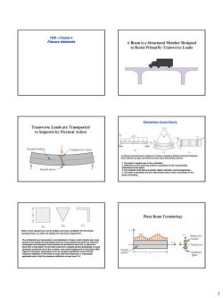
A Beam is a Structural Member Designed to Resist Primarily Transverse Loads Elemontary beam theory Transverse Loads are Transported to Supports by Flexural Action ,10 Compressive stress 7aaoea Plane Beam Terminology (a) (b) (e) gww 802anh9a866 1
1 FEM – Chapter 4 Flexure elements Elementary beam theory (a) Simply supported beam subjected to arbitrary (negative) distributed load.(b) Deflected beam element. (c) Sign convention for shear force and bending moment. 1. The beam is loaded only in the y direction. 2. Deflections of the beam are small in comparison to the characteristic dimensions of the beam. 3. The material of the beam is linearly elastic, isotropic, and homogeneous. 4. The beam is prismatic and the cross section has an axis of symmetry in the plane of bending. Beam cross sections:(a) and (b) satisfy symmetry conditions for the simple bending theory, (c) does not satisfy the symmetry requirement. The ramifications of assumption 4 are illustrated in Figure, which depicts two cross sections that satisfy the assumption and one cross section that does not. Both the rectangular and triangular cross sections are symmetric about the xy plane and bend only in that plane. On the other hand, the L-shaped section possesses no such symmetry and bends out of the xy plane, even under loading only in that plane. With regard to the figure, assumption 2 can be roughly quantified to mean that the maximum deflection of the beam is much less than dimension h. A generally applicable rule is that the maximum deflection is less than 0.1h
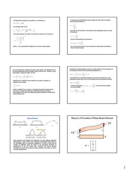
the bending strain is then 4.4志.p-n-p地。 ” ,==-E,片 Flexure Elemen Degrees of Freedom of Plane Beam Element △☒ 2
2 the length after bending at any position y is expressed as: the bending strain is then From basic calculus, the radius of curvature of a planar curve is given by where v = v(x) represents the deflection curve of the neutral surface. In keeping with small deflection theory, slopes are also small, so Equation above is approximated by such that the normal strain in the direction of the longitudinal axis as a result of bending is and the corresponding normal stress is So at a given cross section, the normal stress varies linearly with distance from the neutral surface. As no net axial force is acting on the beam cross section, the resultant force of the stress distribution given by Equation above must be zero. Therefore, at any axial position x along the length, we have Noting that at an arbitrary cross section the curvature is constant, so Equation above implies which is satisfied if the xz plane (y = 0) passes through the centroid of the area.Thus, we obtain the well-known result that the neutral surface is perpendicular to the plane of bending and passes through the centroid of the cross-sectional area. Similarly, the internal bending moment at a cross section must be equivalent to the resultant moment of the normal stress distribution, so The integral term in Equation represents the moment of inertia of the cross sectional area about the z axis, so the bending moment expression becomes Combining Equations , we obtain the normal stress equation for beam bending: Flexure Element Beam elements with identical end deflections but quite different deflection characteristics. Figures below show physically unacceptable discontinuity at the connecting node, so transverse deflection of a beam is such that the variation of deflection along the length is not adequately described by displacement of the end points only. Therefore, the flexure element formulation must take into account the slope (rotation) of the beam as well as end-point displacement
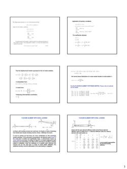
=有4.n, 417 Thus the disp =(-÷n(-¥州 医附图…俗会… FLEXURE ELEMENT WITHAXIAL LOADING FLEXURE ELEMENT WITH AXIAL LOADING m 清运 陶-巴 3
3 Application of boundary conditions: The coefficients obtained: Thus the displacement function expressed in form of nodal variables: In interpolation form: In matrix form: Introducing dimensionless coordinates: the normal stress distribution on a cross section located at axial position x: For the FLEXURE ELEMENT STIFFNESS MATRIX, Please refer to textbook for the details. FLEXURE ELEMENT WITH AXIAL LOADING (a) Beam with bending moment and axial load. (b) Section of beam, illustrating how tensile load reduces bending moment, hence, “stiffening” the beam. It must be pointed out that there are many ramifications to this seemingly simple extension. If the axial load is compressive, the element could buckle. If the axial load is tensile and significantly large, a phenomenon known as stress stiffening can occur. As shown in Figure b, in a beam subjected to both transverse and axial loading, the effect of the axial load on bending is directly related to deflection, since the deflection at a specific point becomes the moment arm for the axial load. In cases of small elastic deflection, the additional bending moment attributable to the axial loading is negligible. FLEXURE ELEMENT WITH AXIAL LOADING simply add the spar element stiffness matrix to the flexure element stiffness matrix to obtain the 6 × 6 element stiffness matrix for a flexure element with axial loading as a non-coupled superposition of axial and bending stiffness

GENERAL THREE-DIMENSIONAL BEAM ELEMENT [时] 信管县息 CLOSING REMARKS Frame structures analysis Members in a frame are considered to be rigidly connected.Both forces and moments 4
4 (a) Nodal displacements in the element coordinate system. (b) Nodal displacements in the global coordinate system. Reorder the element stiffness matrix: The element displacements are written in terms of the global displacements as: in matrix form: it is readily shown that the 6 × 6 element stiffness matrix in the global system is given by: where [R] is the transformation matrix that relates element displacements to global displacements. A GENERAL THREE-DIMENSIONAL BEAM ELEMENT (a) Three-dimensional beam element. (b) Nodal displacements in element xz plane. The element equilibrium equations for a two-plane bending element with axial stiffness are written in matrix form as: Adding the torsional characteristics to the general beam element, the element equations become: CLOSING REMARKS In this chapter, finite elements for beam bending are formulated using elastic flexure theory from elementary strength of materials. The resulting elements are very useful in modeling frame structures in two or three dimensions. A general three-dimensional beam element including axial, bending, and torsional effects is developed by, in effect, superposition of a spar element, two flexure elements, and a torsional element. In development of the beam elements, stiffening of the elements owing to tensile loading, the possibility of buckling under compressive axial loading, and transverse shear effects have not been included. In most commercial finite element software packages, each of these concerns is an option that can be taken into account at the user’s discretion. Frame structures analysis Members in a frame are considered to be rigidly connected. Both forces and moments can be transmitted through their joints. We need the general beam element (combination of bar and simple beam elements) to model frames
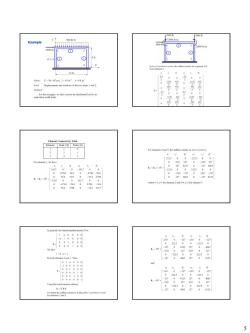
2000b- Example and rot o joints I and 2 。 k=k=0 。 A-PT 5
5 Example

卧三 Example problem The beam ABC is clamped at the left side and simply supported at the right side Dimensions are in m,forces in N and 7290- loading q in N/m.Also,E/=104 Nm2.At x Find the Finite element discretization Stiffness of element 1 We consider 2 beam elements as follows: 123 3456·—8 阳州场2 5m4 6
6
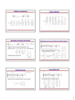
Stiffness of element 2 Global stiffness 3456 K-10 世世 Boundary moments and forces Distributed load and concentrated load inside the element F-tL .a-efa Assembly of this vector gives: Distributed load Assembled load 公-wr片 Element 2has concentrated load Pat an end point tions gives: 153 12345 7
7

Solution step Solution step 5.6 09420 75 :-伦}做 Displacement field Moments and shear forces For element 1: =整=袋g袋1w=-,3 -心a -N+ ”-a登鉴袋袋% For element 2: w-a-myg學-ms -N -吧:+NA:+N+N B华m袋学学的-m Place nodes on location of concentrated loac Results with refined grids:3 elements 1 | R
8
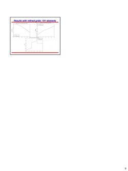
Results with refined grids:101 elements 9
9
按次数下载不扣除下载券;
注册用户24小时内重复下载只扣除一次;
顺序:VIP每日次数-->可用次数-->下载券;
- 同济大学:《有限元方法》课程教学资源(教案讲义)Chapter 3 Direct Stiffness Method(DSM).pdf
- 同济大学:《有限元方法》课程教学资源(教案讲义)Chapter 2 Stiffness Matrices, Spring and Bar Elements.pdf
- 同济大学:《有限元方法》课程教学资源(教案讲义)Chapter 1 Finite Element Method - Introduction to Finite Element Method.pdf
- 同济大学:《有限元方法》课程教学资源(试卷习题)WORKSHOP 10 SUPPORT BRACKET.pdf
- 同济大学:《有限元方法》课程教学资源(试卷习题)考核试卷(A卷)2011-2012学年第1学期(含解答).pdf
- 《基础工程》课程教学资源(参考资料)中华人民共和国行业标准(JTG D63-2007)公路桥涵地基及基础设计规范(报批初稿)Code for Design of Ground Base and Foundation of Highway Bridges and Culverts.pdf
- 《基础工程》课程教学资源(参考资料)中华人民共和国行业标准(JTG D62-2004)公路钢筋混凝土及预应力混凝土桥涵设计规范 Code for Design of Highway Reinforced Concrete and Prestressed Concrete Bridges and Culverts.pdf
- 《基础工程》课程教学资源(参考资料)中华人民共和国行业标准(JTG D61-2005)公路圬工桥涵设计规范.pdf
- 《基础工程》课程PPT教学课件(英文讲稿)Chapter 09 Sheet-Pile Walls(Cantilevered and Anchored).ppt
- 《基础工程》课程PPT教学课件(英文讲稿)Chapter 08 Mechanically Stabilized Earth and Concrete Retaining Walls.ppt
- 《基础工程》课程PPT教学课件(英文讲稿)Chapter 07 Mat Foundation.ppt
- 《基础工程》课程PPT教学课件(英文讲稿)Chapter 06 Special footings and beams on the elastic foundations.ppt
- 《基础工程》课程PPT教学课件(英文讲稿)Chapter 05 Spread footing design.ppt
- 《基础工程》课程PPT教学课件(英文讲稿)Chapter 04 Factors to consider in foundation design.ppt
- 《基础工程》课程PPT教学课件(英文讲稿)Chapter 03 Improving Site Soils for Foundation Use.ppt
- 《基础工程》课程PPT教学课件(英文讲稿)Chapter 02 基础承载力 Bearing capacity of foundation(2/2).ppt
- 《基础工程》课程PPT教学课件(英文讲稿)Chapter 02 基础承载力 Bearing capacity of foundation(1/2).ppt
- 《基础工程》课程PPT教学课件(英文讲稿)Chapter 02 Bearing capacity of foundations.ppt
- 《基础工程》课程PPT教学课件(英文讲稿)Chapter 10 Single Piles(2/2).ppt
- 《基础工程》课程PPT教学课件(英文讲稿)Chapter 10 Single Piles(1/2).ppt
- 同济大学:《有限元方法》课程教学资源(教案讲义)Chapter 6 Interpolation Functions for General Element Formulation.pdf
- 同济大学:《有限元方法》课程教学资源(教案讲义)Chapter 7 Isoparametric Element.pdf
- 同济大学:《有限元方法》课程教学资源(教案讲义)Chapter 8 Practical modeling Issues.pdf
- 北京化工大学:《过程设备设计》课程教学资源(课件讲稿)第四章 压力容器设计 Design of Pressure Vessels 4.3 常规设计 4.3.4 密封装置设计.pdf
- 上海海洋大学:工程学院2011年版课程教学大纲汇编(正文).pdf
- 上海海洋大学:食品学院2018年版课程教学大纲汇编(能源与动力、建筑环境专业).pdf
- 上海海洋大学:工程学院2018版课程教学大纲汇编(工业工程专业).pdf
- 上海海洋大学:工程学院2018版课程教学大纲汇编(其他).pdf
- 上海海洋大学:工程学院创新课程教学大纲合集(2022年版).pdf
- 上海海洋大学:工程学院各专业课程教学大纲汇编(2022年版).pdf
- 吉林大学:《工程地质学基础》课程电子教案(PPT课件)第一章 土的物质组成与结构、构造.ppt
- 吉林大学:《工程地质学基础》课程电子教案(PPT课件)绪论(负责人:李广杰).ppt
- 吉林大学:《工程地质学基础》课程电子教案(PPT课件)第三章 土的力学性质.ppt
- 吉林大学:《工程地质学基础》课程电子教案(PPT课件)第二章 土的物理性质.ppt
- 吉林大学:《工程地质学基础》课程电子教案(PPT课件)第五章 活断层和地震工程地质研究.ppt
- 吉林大学:《工程地质学基础》课程电子教案(PPT课件)第六章 斜坡变形破坏工程地质研究.ppt
- 吉林大学:《工程地质学基础》课程电子教案(PPT课件)第四章 岩石的工程地质性质.ppt
- 吉林大学:《工程地质学基础》课程电子教案(PPT课件)第七章 房屋建筑和构筑物工程地质勘察.ppt
- 大连大学:工程管理专业课程教学大纲汇编(2010).doc
- 大连理工大学:《测量学》课程教学实验(课件讲义)测量实验与数字化测量实习指导书(修编).doc
