同济大学:《空气动力学》课程教学资源(试卷习题)试卷 Final
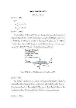
AERODYNAMICS (Take-home Exam) Problem 1 (5%) Expand: ad@o 品ixO Problem 2 (10%) An aircraft from the Boeing 747-family is flying at cruise speed at steady level flight(see figure2).The aircraft's maximum cruise speed is55923 mph,its mass ism =400000 kg.the lift force is provided by the wing,with surface area Sw=523m2, while the thrust is provided by 3 engines,each of them developing a power at cruise speed of P=15.75MW.Calculate both the lift and drag coefficients. Boeing 747 Aircraft m=400,000kg Wing Surface Area Sw=523m2 Venuse=559.23 mph Vcruise W Figure 2:Steady level flight conditions for a Boeing 747. Problem 3(10%) The lift force L (unknown)on a missile is a function of its length L,velocity V, diameter D,angle of attack a density p,viscosityand speed of sound c of the air. Use dimensional analysis(Buckingham-Pi Theorem)to obtain the dependence of the non-dimensionalized lift force as a function of other non-dimensional groups. Problem 4 (10%)
AERODYNAMICS (Take-home Exam) Problem 1 (5%) Expand: Problem 2 (10%) An aircraft from the Boeing 747-family is flying at cruise speed at steady level flight (see figure 2). The aircraft's maximum cruise speed is 559.23 mph, its mass is m = 400000 kg, the lift force is provided by the wing, with surface area Sw = 523m², while the thrust is provided by 3 engines, each of them developing a power at cruise speed of P = 15.75MW. Calculate both the lift and drag coefficients. Figure 2: Steady level flight conditions for a Boeing 747. Problem 3 (10%) The lift force L (unknown) on a missile is a function of its length l, velocity V, diameter D, angle of attack α, density ρ, viscosity τ, and speed of sound c of the air. Use dimensional analysis (Buckingham-Pi Theorem) to obtain the dependence of the non-dimensionalized lift force as a function of other non-dimensional groups. Problem 4 (10%)
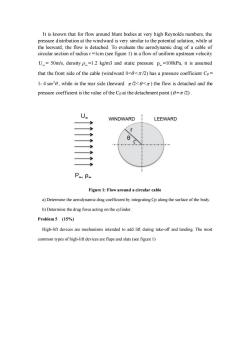
It is known that for flow around blunt bodies at very high Reynolds numbers,the ribution at the win ward is very similar to the potential solution,while a the flow is detached.To evaluate the aerodynamic drag of a cable of circular section of radiusr=1cm(see figure 1)in a flow of uniform upstream velocity U=50m/s,densityp=1.2 kg/m3 and static pressure p=100kPa,it is assumed that the front side of the cable(windward<2)has a pressure coefficient Cp= 1-4sin0,while in the rear side (leeward)the flow is detached and the pressure coefficient is the value of the Cpat the detachment point(=2). U WINDWARD LEEWARD r P.P Figure 1:Flow around a circular cable a)Determine the aerodynamic drag coefficient by integrating Cp along the surface of the body b)Determine the drag force acting on the ylinder Problem5 (15%) High-lift devices are mechanisms intended to add lift during take-off and landing.The most common types ofhigh-lift devices are flaps and slats(see figure 1)
It is known that for flow around blunt bodies at very high Reynolds numbers, the pressure distribution at the windward is very similar to the potential solution, while at the leeward, the flow is detached. To evaluate the aerodynamic drag of a cable of circular section of radius r =1cm (see figure 1) in a flow of uniform upstream velocity U = 50m/s, density =1.2 kg/m3 and static pressure p =100kPa, it is assumed that the front side of the cable (windward 0< < /2) has a pressure coefficient Cp = 1- 4 2 sin , while in the rear side (leeward /2< < ) the flow is detached and the pressure coefficient is the value of the Cp at the detachment point ( = /2) . Figure 1: Flow around a circular cable a) Determine the aerodynamic drag coefficient by integrating Cp along the surface of the body. b) Determine the drag force acting on the cylinder. Problem 5 (15%) High-lift devices are mechanisms intended to add lift during take-off and landing. The most common types of high-lift devices are flaps and slats (see figure 1)
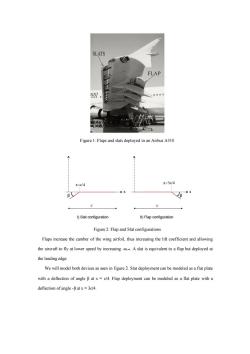
SLATS 9 Figure 1:Flaps and slats deployed in an Airbus A310 x=3c/4 -≥X I)Slat configuration ll)Flap configuration Figure2:Flap and Slat configurations Flaps increase the camber of the wing airfoil,thus increasing the if coefficient and allowing the aircraft to fly at lower speed by increasingAslat is equivalent to a flap but deployed at the leading edge. We will model both devices as seen in figure2.Slat deployment can be modeled as a flat plate with a deflection of angle B at x=c/4.Flap deployment can be modeled as a flat plate with a deflection of angle-Batx=3c/4
Figure 1: Flaps and slats deployed in an Airbus A310 Figure 2: Flap and Slat configurations Flaps increase the camber of the wing airfoil, thus increasing the lift coefficient and allowing the aircraft to fly at lower speed by increasing -αL=0. A slat is equivalent to a flap but deployed at the leading edge. We will model both devices as seen in figure 2. Slat deployment can be modeled as a flat plate with a deflection of angle β at x = c/4. Flap deployment can be modeled as a flat plate with a deflection of angle -β at x = 3c/4
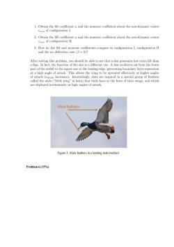
Obthnand the moment coefcent about the aerodynamic cente Obtan the moment coelficient about the erodynamic cnter 3.How do the lift and moment coefficients compare in configuration I,configuration II and the no defection case (=0) After solving this problem,you should be able to see that a slat generates less extra lift than a flap.In fact,the function of the slat is a different one.A slat re-directs air from the lower part of the airfoil to the upper one at the leading edge,preventing boundary layer separation at a high angle of attack.This allows the wing to be operated effectively at higher angles attacka group o tarily at high Alula feathers Figure 3:Alula feathers in a landing male mallard. Problem 6(15%)
Figure 3: Alula feathers in a landing male mallard. Problem 6 (15%)
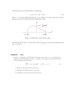
The camber line of an airfoil of chord c is defined as: z()=c(a-x)1-4r2) (2) where e<<1 and the airfoil located at sc/2.Obtain a in order to have the center of pressure at the same location than the aerodynamic center. = cos0 x= / x-ch2 Figure 4:Camber line centered at the origin Note that the camber line is centered at the origin(see figure)thus the transformation will be cos6 PROBLEM7(15%) velocity along the span direction is 0=-1++4g.=2c< 1.Obtain the value of the lift Lof the wing. 2.Determine the induced drag D in the wing 3.Calculate the roll moment about the axis M
PROBLEM 7 (15%)
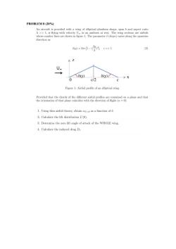
PROBLEM 8 (20%) An aircraft is provided with a wing of elliptical planform shape,span band aspect ratio A>>1,is flying with velocity Uo in an ambient at rest.The wing sections are airfoils whose camber lines are shown in figure 1.The parameter 6(slope)varies along the spanwise direction as )=21-(gA,X 0 c/2 c Figure 1:Airfoil profile of an elliptical wing Provided that the chords of the different airfoil profiles are contained on a plane and that the orientation of that plane coincides with the direction of flight(a=0): 1.Using thin airfoil theory,obtain aL as a function of 6 2.Calculate the lift distribution L'(0). 3.Determine the zero lift angle of attack of the WHOLE wing. 4.Calculate the induced drag Di
PROBLEM 8 (20%)
按次数下载不扣除下载券;
注册用户24小时内重复下载只扣除一次;
顺序:VIP每日次数-->可用次数-->下载券;
- 同济大学:《空气动力学》课程电子教案(课件讲稿)Chapter 3 Fundamentals of Inviscid Inviscid, Incompressible Flow.pdf
- 同济大学:《空气动力学》课程电子教案(课件讲稿)Chapter 2 Some Fundamental Principles and Equations.pdf
- 同济大学:《空气动力学》课程电子教案(课件讲稿)Chapter 1 Introduction to Aerodynamics(负责人:金哲岩).pdf
- 长沙理工大学:《热力发电厂》课程教学资源(作业习题,无答案)第六章.docx
- 长沙理工大学:《热力发电厂》课程教学资源(作业习题,无答案)第五章.docx
- 长沙理工大学:《热力发电厂》课程教学资源(作业习题,无答案)第四章.docx
- 长沙理工大学:《热力发电厂》课程教学资源(作业习题,无答案)第三章.docx
- 长沙理工大学:《热力发电厂》课程教学资源(作业习题,无答案)第二章.docx
- 长沙理工大学:《热力发电厂》课程教学资源(作业习题,无答案)第一章.doc
- 长沙理工大学:《热力发电厂》课程教学资源(参考资料)湖南华润电力鲤鱼江有限公司300MW火电机组培训教材《锅炉设备及系统》电子版(共十四章).pdf
- 长沙理工大学:《热力发电厂》课程教学资源(参考资料)湖南华润电力鲤鱼江有限公司300MW火电机组培训教材《燃料运输设备及系统》电子版(共二十二章).pdf
- 长沙理工大学:《热力发电厂》课程教学资源(参考资料)湖南华润电力鲤鱼江有限公司300MW火电机组培训教材《汽轮机设备及系统》电子版.pdf
- 《热力发电厂》课程教学资源(教案讲义)热力发电厂授课教案教材(共八章).doc
- 华北电力大学:《热力发电厂》课程教学资源(讲稿)原则性热力系统与全面性热力系统.pdf
- 长沙理工大学:《热力发电厂》课程教学资源(参考资料)热力发电厂课程设计.pdf
- 《热力发电厂》课程教学资源(参考资料)热力发电厂常用计算符号表.doc
- 《热力发电厂》课程教学资源(参考资料)热力发电厂常用英语技术词汇.doc
- 《热力发电厂》课程教学资源(参考资料)汽机系统图例集.pdf
- 《热力发电厂》课程教学资源(参考资料)发电站热力系统图.pdf
- 长沙理工大学:《热力发电厂》课程教学资源(大纲教案)授课教案 Thermal Power Plant.pdf
- 上海海洋大学:食品学院能源与动力工程和建筑环境与能源应用工程专业教学大纲汇编(2022年版).pdf
- 《电力系统继电保护原理》课程教学资源(文献资料)国家电网公司电力安全工作规程.pdf
- 《电力系统继电保护原理》课程教学资源(文献资料)电气规范汇编.doc
- 《电力系统继电保护原理》课程教学资源(试卷习题)电力系统继电保护题库(共三部分,含参考答案).doc
- 《电力系统继电保护原理》课程教学资源(试卷习题)电力系统继电保护练习题库(含参考答案).pdf
- 《电力系统继电保护原理》课程教学资源(PPT讲稿)继电保护和安全自动装置面临的问题与需要开展的研究(西安交通大学:张保会).ppt
- 华北电力大学:《电力系统继电保护原理》课程教学资源(PPT讲稿)继电保护技术的发展.ppt
- 石河子大学:《电力系统继电保护原理》课程教学资源(试卷习题)继电保护各章习题集(打印版,含答案).pdf
- 《电力系统继电保护原理》课程教学资源(PPT讲稿)对数字化保护的认识(西安交通大学:索南加乐).ppt
- 高等学校教材:《电力系统继电保护原理》教学参考书(第三版)电力系统继电保护原理PDF电子版(共八章,天津大学:贺家李、宋从矩).pdf
- 21世纪高等院校教材:《电力系统继电保护原理及新技术》教学教材电子书(共九章,PDF电子版,主编:李佑光、林东).pdf
- 石河子大学:《电力系统继电保护原理》课程教学资源(电子教案)电力系统继电保护原理教案(负责人:王洪坤,打印版).pdf
- 石河子大学:《电力系统继电保护原理》课程教学资源(实验指导)电力系统继电保护原理实验指导书(共五个实验,含附录,打印版).pdf
- 石河子大学:《电力系统继电保护原理》课程教学资源(实验指导)电力系统继电保护原理课程设计指导书(打印版).pdf
- 石河子大学:《电力系统继电保护原理》课程教学资源(教案大纲)电力系统综合课程设计 Comprehensuve Course Design of Power System.doc
- 石河子大学:《电力系统继电保护原理》课程教学资源(教案大纲)电力系统综合实验教学大纲.doc
- 石河子大学:《电力系统继电保护原理》课程教学资源(教案大纲)电力系统继电保护原理 Principle of Protection Relay.pdf
- 石河子大学:《电力系统继电保护原理》课程教学资源(教案大纲)电力系统继电保护原理实验教学大纲.pdf
- 石河子大学:《电力系统继电保护原理》课程教学资源(教案大纲)电力系统继电保护原理教学大纲(2013版).doc
- 石河子大学:《电力系统继电保护原理》课程教学资源(PPT课件)第十章 电力变压器保护.ppt
