《电力电子技术》课程教学资源(参考资料)gto器件5SGA30j2501

VDRM =2500V Gate turn-off Thyristor ITGOM 3000A ITSM = 30 kA 1.50V 5SGA30J2501 = 0.33m2 Voclin 1400 V Doc.N0.5SYA1213-02Aug.2000 Patented free-floating silicon technology Low on-state and switching losses Annular gate electrode Industry standard housing Cosmic radiation withstand rating Blocking VDRM Repetitive peak off-state voltage 2500VVeR≥2V VRRM Repetitive peak reverse voltage 17V Repetitive peak off-state current 100 mA Vo VDRM VGR≥2V IRRM Repetitive peak reverse current 50 mA VR=VRRM RGK=00 Permanent DC voltage for 100 1400V -40s T s 125C.Ambient cosmic radiation at sea level in open air. Mechanical data (see Fig.4) Fm Mounting force min. 36kN max. 44 kN Acceleration: Device unclamped 50 m/s2 Device clamped 200m/s2 M Weight 1.3 Ds Surface creepage distance 233 mm Da Air strike distance mm ABB Semiconductors AG reserves the right to change specifications without notice ABB
ABB Semiconductors AG reserves the right to change specifications without notice. VDRM = 2500 V ITGQM = 3000 A ITSM = 30 kA VT0 = 1.50 V rT = 0.33 mΩ VDClin = 1400 V Gate turn-off Thyristor 5SGA 30J2501 Doc. No. 5SYA 1213-02 Aug. 2000 • Patented free-floating silicon technology • Low on-state and switching losses • Annular gate electrode • Industry standard housing • Cosmic radiation withstand rating Blocking VDRM Repetitive peak off-state voltage 2500 V VGR ≥ 2V VRRM Repetitive peak reverse voltage 17 V IDRM Repetitive peak off-state current ≤ 100 mA VD = VDRM VGR ≥ 2V IRRM Repetitive peak reverse current ≤ 50 mA VR = VRRM RGK = ∞ VDClink Permanent DC voltage for 100 FIT failure rate 1400 V -40 ≤ Tj ≤ 125 °C. Ambient cosmic radiation at sea level in open air. Mechanical data (see Fig. 4) Fm min. 36 kN Mounting force max. 44 kN A Acceleration: Device unclamped Device clamped 50 200 m/s2 m/s2 M Weight 1.3 kg DS Surface creepage distance ≥ 33 mm Da Air strike distance ≥ 15 mm

5SGA30J2501 GTO Data On-state ITAVM Max.average on-state current 1300A I Half sine wave.Te=85C Max.RMS on-state current 2040A Max.peak non-repetitive 30 kA tp 10msT=125℃ surge current 51 kA tp 1 ms After surge: Limiting load integral 4.50105A2s tp 10 ms Vo=VR=OV 1.30-10A2 tp 1 ms V On-state voltage 2.50V = 3000A VTo Threshold voltage 1.50V r=400-4000AT=125℃ In Slope resistance 0.33m2 H Holding current 100AT=25C Gate Gate trigger voltage 1.2V Vo =24V T=25℃ Gate trigger current 4.0A Ra=0.12 VGRM Repetitive peak reverse voltage 17V Repetitive peak reverse current 50 mA VGR VGRM Turn-on switching di/dt Max.rate of rise of on-state 500A/wsf=200Hz=3000A,T=125℃ current 1000A/us f=1Hz lGM =30 A,die/dt=20 A/us ta Delay time 2.5μs Vo 0.5 VDRM T=125℃ t Rise time 5.0μs h= 3000 A di/dt 300 A/us tonmin Min.on-time 100μs 30A 20 A/us Eon Turn-on energy per pulse 2.00Ws Cs 5uF Rs 52 Turn-off switching Max controllable turn-off 3000A digo/dt 40 A/us current Cs =5uF Ls ≤0.3H Storage time 25.0s Vo =VDRM VoM =VDRM t Fall time 3.0μs Ti 125C digo/dt 40 A/us Min.off-time 100s Turn-off energy per pulse 4.7Ws Cs 5 UF Rs =52 IGoM Peak turn-off gate current 1000A Ls≤0.3H erves the right to page 2 of6
5SGA 30J2501 ABB Semiconductors AG reserves the right to change specifications without notice. Doc. No. 5SYA 1213-02 Aug. 2000 page 2 of 6 GTO Data On-state ITAVM Max. average on-state current 1300 A Half sine wave, TC = 85 °C ITRMS Max. RMS on-state current 2040 A ITSM 30 kA tP = 10 ms Tj Max. peak non-repetitive = 125°C surge current 51 kA tP = 1 ms After surge: I 2 t Limiting load integral 4.50⋅106 A2 s tP = 10 ms VD = VR = 0V 1.30⋅106 A2 s tP = 1 ms VT On-state voltage 2.50 V IT = 3000 A VT0 Threshold voltage 1.50 V IT = 400 - 4000 A Tj = 125 °C rT Slope resistance 0.33 mΩ IH Holding current 100 A Tj = 25 °C Gate VGT Gate trigger voltage 1.2 V VD = 24 V Tj = 25 °C IGT Gate trigger current 4.0 A RA = 0.1 Ω VGRM Repetitive peak reverse voltage 17 V IGRM Repetitive peak reverse current 50 mA VGR = VGRM Turn-on switching di/dtcrit Max. rate of rise of on-state 500 A/µs f = 200Hz IT = 3000 A, Tj = 125 °C current 1000 A/µs f = 1Hz IGM = 30 A, diG/dt = 20 A/µs td Delay time 2.5 µs VD = 0.5 VDRM Tj = 125 °C tr Rise time 5.0 µs IT = 3000 A di/dt = 300 A/µs ton(min) Min. on-time 100 µs IGM = 30 A diG/dt = 20 A/µs Eon Turn-on energy per pulse 2.00 Ws CS = 5 µF RS = 5 Ω Turn-off switching ITGQM Max controllable turn-off 3000 A VDM = VDRM diGQ/dt = 40 A/µs current CS = 5 µF LS ≤ 0.3 µH ts Storage time 25.0 µs VD = ½ VDRM VDM = VDRM tf Fall time 3.0 µs Tj = 125 °C diGQ/dt = 40 A/µs toff(min) Min. off-time 100 µs ITGQ = ITGQM Eoff Turn-off energy per pulse 4.7 Ws CS = 5 µF RS = 5 Ω IGQM Peak turn-off gate current 1000 A LS ≤ 0.3 µH

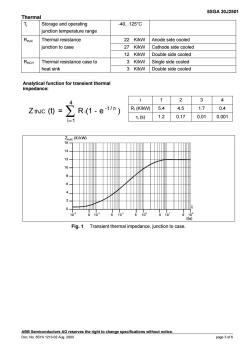
5SGA30J2501 Therma T Storage and operating 40.125°C junction temperature range Thermal resistance 22 K/kW Anode side cooled junction to case 27 K/kW Cathode side cooled 12 K/kW Double side cooled Thermal resistance case to 3 K/kW Single side cooled heat sink 3 K/kW Double side cooled unction for transient therma i1234 2 R(1-e-t) R(K/kW05.44.51.70.4 s)1.20.170.010.001 (K/kw) 14 12- 10 2 0 102 610 510 Fig.1 Transient thermal impedance,junction to case s the right to change specifications without notice page 3of6
5SGA 30J2501 ABB Semiconductors AG reserves the right to change specifications without notice. Doc. No. 5SYA 1213-02 Aug. 2000 page 3 of 6 Thermal Tj Storage and operating -40.125°C junction temperature range RthJC Thermal resistance 22 K/kW Anode side cooled junction to case 27 K/kW Cathode side cooled 12 K/kW Double side cooled RthCH Thermal resistance case to 3 K/kW Single side cooled heat sink 3 K/kW Double side cooled i 12 3 4 RI (K/kW) 5.4 4.5 1.7 0.4 Analytical function for transient thermal impedance: Z (t) = R (1 - e ) 4 i 1 -t / thJC ∑ i = τi τi (s) 1.2 0.17 0.01 0.001 Fig. 1 Transient thermal impedance, junction to case

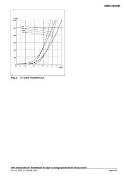
5SGA30J2501 [A Fig.2 On-state characteristics page 4 of 6
5SGA 30J2501 ABB Semiconductors AG reserves the right to change specifications without notice. Doc. No. 5SYA 1213-02 Aug. 2000 page 4 of 6 Fig. 2 On-state characteristics

5SGA30J2501 Anode V /di/dt 0.9V% 0.90 0 VDSP v(t) 0.1 0.25a Gate dia/dt 9 0.1 0.1e ve(t) 0.1 dico/dt Fig.3 General current and voltage waveforms with GTO-specific symbols Fg.4amesm8,em"ees unless stated otherwise. ABB Semiconductors aG reserves the riaht to ch ge 00c.N0.5SYA1213-02Aug.2000 hout notic page5 of6
5SGA 30J2501 ABB Semiconductors AG reserves the right to change specifications without notice. Doc. No. 5SYA 1213-02 Aug. 2000 page 5 of 6 Fig. 3 General current and voltage waveforms with GTO-specific symbols Fig. 4 Outline drawing. All dimensions are in millimeters and represent nominal values unless stated otherwise

5SGA30J2501 Reverse avalanche capability In operation with an antiparallel freewheeling diode.the GTO reverse voltage VR may exceed the rat value due to stray inductance and diode turn-on voltage spike at high di/dt.The GTO is then driven into reverse avalanche.This condition is not dangerous for the GTO provided avalanche time uring this time ABB Semiconductors AG reserves the right to change specifications without notice. ABB ABB Semiconductors AG D0GN0.5SYA1213-02Ag.2000
5SGA 30J2501 ABB Semiconductors AG reserves the right to change specifications without notice. ABB Semiconductors AG Doc. No. 5SYA 1213-02 Aug. 2000 Fabrikstrasse 2 CH-5600 Lenzburg, Switzerland Tel: +41 (0)62 888 6419 Fax: +41 (0)62 888 6306 E-mail info@ch.abb.com Internet www.abbsem.com Reverse avalanche capability In operation with an antiparallel freewheeling diode, the GTO reverse voltage VR may exceed the rate value VRRM due to stray inductance and diode turn-on voltage spike at high di/dt. The GTO is then driven into reverse avalanche. This condition is not dangerous for the GTO provided avalanche time and current are below 10 µs and 1000 A respectively. However, gate voltage must remain negative during this time. Recommendation : VGR = 10. 15 V
按次数下载不扣除下载券;
注册用户24小时内重复下载只扣除一次;
顺序:VIP每日次数-->可用次数-->下载券;
- 《电工学》课程PPT教学课件(电工技术)第四章 正弦交流电路.pps
- 《电工学》课程PPT教学课件(电工技术)第十章 继电接触器控制系统.pps
- 《电工学》课程PPT教学课件(电工技术)第六章 磁路与铁心线圈电路.ppt
- 《电工学》课程PPT教学课件(电工技术)第七章 交流电动机.pps
- 《电工学》课程PPT教学课件(电工技术)第五章 三相电路.pps
- 《电工学》课程PPT教学课件(电工技术)第三章 电路的暂态分析.ppt
- 《电工学》课程PPT教学课件(电工技术)第二章 电路的分析方法.pps
- 《电工学》课程PPT教学课件(电工技术)第一章 电路的基本概念与基本定律.pps
- 《电工学》课程教学资源(PPT课件讲稿)第十六章 基本放大电路.ppt
- 《电工学》课程教学资源(PPT课件讲稿)第十五章 半导体二极管和三极管.ppt
- 《电工学》课程教学资源(PPT课件讲稿)第十二章 可编程控制器及其应用.ppt
- 《电工学》课程教学资源(PPT课件讲稿)第十九章 直流稳压电源.ppt
- 《电工学》课程教学资源(PPT课件讲稿)第十七章 集成运算放大器.ppt
- 《电工学》课程教学资源(PPT课件讲稿)第十一章 继电接触器控制系统.ppt
- 《电工学》课程教学资源(PPT课件讲稿)第七章 异步电动机.ppt
- 《电工学》课程教学资源(PPT课件讲稿)第四章 正弦交流电路.ppt
- 《电工学》课程教学资源(PPT课件讲稿)第六章 磁路与铁心线圈电路.ppt
- 《电工学》课程教学资源(PPT课件讲稿)第五章 三相电路.ppt
- 《电工学》课程教学资源(PPT课件讲稿)第三章 电路的暂态分析.ppt
- 《电工学》课程教学资源(PPT课件讲稿)第二章 电路的分析方法.ppt
- 《电力电子技术》课程教学资源(参考资料)IGBT器件1 IGBT.pdf
- 《电力电子技术》课程教学资源(参考资料)IGBT器件2 IGBT-INTRO.pdf
- 《电力电子技术》课程教学资源(参考资料)MOSFET器件 mosfet.pdf
- 《电力电子技术》课程教学资源(参考资料)晶闸管 scr.pdf
- 《电力电子技术》课程教学资源(参考资料)器件小结 Classification.pdf
- 石河子大学:《电力电子技术》课程教学实验指导书(精简).doc
- 《电力电子技术》课程教学资源(参考资料)MOS管 8N60.pdf
- 《电力电子技术》课程教学资源(参考资料)97A6,MAC97A6 645 MAC97A6datasheet.pdf
- 《电力电子技术》课程教学资源(参考资料)E13005-2 E13005 NPN晶体管.pdf
- 《电力电子技术》课程教学资源(参考资料)BTA41-600中文资料.pdf
- 《电力电子技术》课程教学资源(参考资料)IRFP450.pdf
- 《电力电子技术》课程教学资源(参考资料)MBR3060PT中文资料.pdf
- 《电力电子技术》课程教学资源(参考资料)三相桥式整流及有源逆变电路的MATLAB仿真.pdf
- 石河子大学:《电力电子技术》课程授课教案(任课教师:龚立娇).doc
- 石河子大学:《电力电子技术》课程教学资源(PPT课件)第1章 绪论(主讲:周伟绩).ppt
- 石河子大学:《电力电子技术》课程教学资源(PPT课件)第2章 电力电子器件.ppt
- 石河子大学:《电力电子技术》课程教学资源(PPT课件)第3章 整流电路.ppt
- 石河子大学:《电力电子技术》课程教学资源(PPT课件)第5章 直流直流变流电路.ppt
- 石河子大学:《电力电子技术》课程教学资源(PPT课件)第4章 逆变电路.ppt
- 石河子大学:《电力电子技术》课程教学资源(PPT课件)第10章 电力电子技术的应用.ppt
