西北农林科技大学:《汽车拖拉机学》课程PPT教学课件(英文版,下册)Chapter 7 Power takeoff systems of tractors
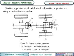
Chapter 7 Tractor's PTO System Section 1 Traction Apparatus Traction apparatus are divided into fixed traction apparatus and swing stem traction apparatus. (a) (b) Figure 7-1 Types of traction apparatus (a)Fixed type (b)Swing stem type 1.Pull blade 2.Jaw 3.Hitch pole Automobile and Tractor Northwest A&F University
Automobile and Tractor Northwest A&F University Chapter 7 Tractor’s PTO System Traction apparatus are divided into fixed traction apparatus and swing stem traction apparatus. Section 1 Traction Apparatus Figure 7-1 Types of traction apparatus (a) Fixed type (b) Swing stem type 1. Pull blade 2. Jaw 3. Hitch pole
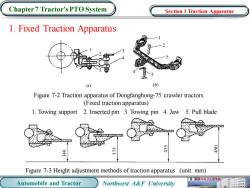
Chapter 7 Tractor's PTO System Section 1 Traction Apparatus 1.Fixed Traction Apparatus (a) (b) Figure 7-2 Traction apparatus of Dongfanghong-75 crawler tractors (Fixed traction apparatus) 1.Towing support 2.Inserted pin 3.Towing pin 4.Jaw 5.Pull blade 065 Figure 7-3 Height adjustment methods of traction apparatus (unit:mm) 业电子工程学膜 Automobile and Tractor Northwest A&F University
Automobile and Tractor Northwest A&F University Chapter 7 Tractor’s PTO System 1. Fixed Traction Apparatus Figure 7-2 Traction apparatus of Dongfanghong-75 crawler tractors (Fixed traction apparatus) 1. Towing support 2. Inserted pin 3. Towing pin 4. Jaw 5. Pull blade Figure 7-3 Height adjustment methods of traction apparatus (unit: mm) Section 1 Traction Apparatus
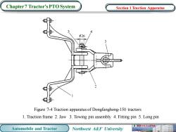
Chapter 7 Tractor's PTO System Section 1 Traction Apparatus h26 Figure 7-4 Traction apparatus of Dongfanghong-150 tractors 1.Traction frame 2.Jaw 3.Towing pin assembly 4.Fitting pin 5.Long pin 机被寿电子工程学原 Automobile and Tractor Northwest A&F University
Automobile and Tractor Northwest A&F University Chapter 7 Tractor’s PTO System Figure 7-4 Traction apparatus of Dongfanghong-150 tractors 1. Traction frame 2. Jaw 3. Towing pin assembly 4. Fitting pin 5. Long pin Section 1 Traction Apparatus
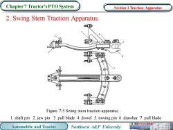
Chapter 7 Tractor's PTO System Section 1 Traction Apparatus 2.Swing Stem Traction Apparatus 伊 Figure 7-5 Swing stem traction apparatus 1.shaft pin 2.jaw pin 3.pull blade 4.dowel 5.towing pin 6.drawbar 7.pull blade 机械与电子工程学膜 Automobile and Tractor Northwest A&F University
Automobile and Tractor Northwest A&F University Chapter 7 Tractor’s PTO System 2. Swing Stem Traction Apparatus Figure 7-5 Swing stem traction apparatus 1. shaft pin 2. jaw pin 3. pull blade 4. dowel 5. towing pin 6. drawbar 7. pull blade Section 1 Traction Apparatus
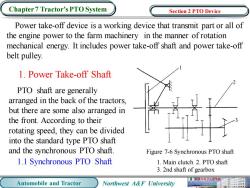
Chapter 7 Tractor's PTO System Section 2 PTO Device Power take-off device is a working device that transmit part or all of the engine power to the farm machinery in the manner of rotation mechanical energy.It includes power take-off shaft and power take-off belt pulley. 1.Power Take-off Shaft PTO shaft are generally arranged in the back of the tractors, but there are some also arranged in the front.According to their rotating speed,they can be divided into the standard type PTO shaft and the synchronous PTO shaft. Figure 7-6 Synchronous PTO shaft 1.1 Synchronous PTO Shaft 1.Main clutch 2.PTO shaft 3.2nd shaft of gearbox 业机械电子工程 Automobile and Tractor Northwest A&F University
Automobile and Tractor Northwest A&F University Chapter 7 Tractor’s PTO System Power take-off device is a working device that transmit part or all of the engine power to the farm machinery in the manner of rotation mechanical energy. It includes power take-off shaft and power take-off belt pulley. 1. Power Take-off Shaft PTO shaft are generally arranged in the back of the tractors, but there are some also arranged in the front. According to their rotating speed, they can be divided into the standard type PTO shaft and the synchronous PTO shaft. 1.1 Synchronous PTO Shaft Figure 7-6 Synchronous PTO shaft 1. Main clutch 2. PTO shaft 3. 2nd shaft of gearbox Section 2 PTO Device
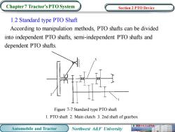
Chapter 7 Tractor's PTO System Section 2 PTO Device 1.2 Standard type PTO Shaft According to manipulation methods,PTO shafts can be divided into independent PTO shafts,semi-independent PTO shafts and dependent PTO shafts. Figure 7-7 Standard type PTO shaft 1.PTO shaft 2.Main clutch 3.2nd shaft of gearbox 械电子工程学酸 Automobile and Tractor Northwest A&F University
Automobile and Tractor Northwest A&F University Chapter 7 Tractor’s PTO System 1.2 Standard type PTO Shaft According to manipulation methods, PTO shafts can be divided into independent PTO shafts, semi-independent PTO shafts and dependent PTO shafts. Figure 7-7 Standard type PTO shaft 1. PTO shaft 2. Main clutch 3. 2nd shaft of gearbox Section 2 PTO Device
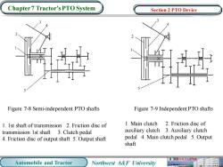
Chapter 7 Tractor's PTO System Section 2 PTO Device Figure 7-8 Semi-independent PTO shafts Figure 7-9 Independent PTO shafts 1.Ist shaft of transmission 2.Friction disc of 1.Main clutch 2.Friction disc of transmission 1st shaft 3.Clutch pedal auxiliary clutch 3.Auxiliary clutch 4.Friction disc of output shaft 5.Output shaft pedal 4.Main clutch pedal 5.Output shaft 机械与电子工程膜 Automobile and Tractor Northwest A&F University
Automobile and Tractor Northwest A&F University Chapter 7 Tractor’s PTO System Figure 7-8 Semi-independent PTO shafts Figure 7-9 Independent PTO shafts 1. 1st shaft of transmission 2. Friction disc of transmission 1st shaft 3. Clutch pedal 4. Friction disc of output shaft 5. Output shaft 1. Main clutch 2. Friction disc of auxiliary clutch 3. Auxiliary clutch pedal 4. Main clutch pedal 5. Output shaft Section 2 PTO Device
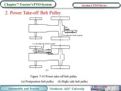
Chapter 7 Tractor's PTO System Section 2 PTO Device 2.Power Take-off Belt Pulley (a)Receding side of belt on upside (b) Figure 7-10 Power take-off belt pulley (a)Postposition belt pulley (b)Right side belt pulley Automobile and Tractor Northwest A&F University
Automobile and Tractor Northwest A&F University Chapter 7 Tractor’s PTO System 2. Power Take-off Belt Pulley (a) Postposition belt pulley (b) Right side belt pulley Figure 7-10 Power take-off belt pulley Section 2 PTO Device
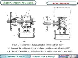
Chapter 7 Tractor's PTO System Section 2 PTO Device (a) (b) Figure 7-11 Diagram of changing rotation direction of belt pulley (a)Changing the position of driving bevel gear (b)Rotating the housing 180 1.PTO shaft 2.Housing 3.Driving bevel gear 4.Driven bevel gear 5.Belt pulley 机被寿电子工程原 Automobile and Tractor Northwest A&F University
Automobile and Tractor Northwest A&F University Chapter 7 Tractor’s PTO System Figure 7-11 Diagram of changing rotation direction of belt pulley (a) Changing the position of driving bevel gear (b) Rotating the housing 180° 1. PTO shaft 2. Housing 3. Driving bevel gear 4. Driven bevel gear 5. Belt pulley Section 2 PTO Device
Chapter 7 Tractor's PTO System Section 3 Hydraulic Lift Hitch The devices using hydraulic to lift and control the farm machinery is called the hydraulic lift hitch.Its functions are as follows:connecting and towing the farm machinery,manipulating the upward and downward of farm machinery,controlling the tilth or hoisting height of the farm machinery,gaining weight to the driving wheels to improve the adhesion property and transmitting the hydraulic energy to the operating machinery for other operations. Hydraulic lift hitch is composed by the hydraulic system,control mechanism and suspension gear. 械电子工程学 Automobile and Tractor Northwest A&F University
Automobile and Tractor Northwest A&F University Chapter 7 Tractor’s PTO System The devices using hydraulic to lift and control the farm machinery is called the hydraulic lift hitch. Its functions are as follows: connecting and towing the farm machinery, manipulating the upward and downward of farm machinery, controlling the tilth or hoisting height of the farm machinery , gaining weight to the driving wheels to improve the adhesion property and transmitting the hydraulic energy to the operating machinery for other operations. Hydraulic lift hitch is composed by the hydraulic system, control mechanism and suspension gear. Section 3 Hydraulic Lift Hitch
按次数下载不扣除下载券;
注册用户24小时内重复下载只扣除一次;
顺序:VIP每日次数-->可用次数-->下载券;
- 西北农林科技大学:《汽车拖拉机学》课程PPT教学课件(英文版,下册)Chapter 6 Brake system.ppt
- 西北农林科技大学:《汽车拖拉机学》课程PPT教学课件(英文版,下册)Chapter 5 Steering system.ppt
- 西北农林科技大学:《汽车拖拉机学》课程PPT教学课件(英文版,下册)Chapter 4 Running system.ppt
- 西北农林科技大学:《汽车拖拉机学》课程PPT教学课件(英文版,下册)Chapter 3 Coupling and Drive Axle.ppt
- 西北农林科技大学:《汽车拖拉机学》课程PPT教学课件(英文版,下册)Chapter 2 Transmission.ppt
- 西北农林科技大学:《汽车拖拉机学》课程PPT教学课件(英文版,下册)Chapter 1 Clutch.ppt
- 西北农林科技大学:《汽车拖拉机学》课程PPT教学课件(英文版,下册)Introduction.ppt
- 西北农林科技大学:《汽车拖拉机学》课程PPT教学课件(英文版,上册)Chapter 10 Engine working conditions and features.ppt
- 西北农林科技大学:《汽车拖拉机学》课程PPT教学课件(英文版,上册)Chapter 8 & 9 Starting system & Gasoline ignition system.ppt
- 西北农林科技大学:《汽车拖拉机学》课程PPT教学课件(英文版,上册)Chapter 7 Engine cooling system.ppt
- 西北农林科技大学:《汽车拖拉机学》课程PPT教学课件(英文版,上册)Chapter 6 Lubricating system.ppt
- 西北农林科技大学:《汽车拖拉机学》课程PPT教学课件(英文版,上册)Chapter 5 Gasoline fuel supply system.ppt
- 西北农林科技大学:《汽车拖拉机学》课程PPT教学课件(英文版,上册)Chapter 4 Diesel fuel supply system.ppt
- 西北农林科技大学:《汽车拖拉机学》课程PPT教学课件(英文版,上册)Chapter 3 Ventilation system.ppt
- 西北农林科技大学:《汽车拖拉机学》课程PPT教学课件(英文版,上册)Chapter 2 Crank-connecting rod mechanism and parts.ppt
- 西北农林科技大学:《汽车拖拉机学》课程PPT教学课件(英文版,上册)Chapter 1 Basic structure and principle of the engine.ppt
- 西北农林科技大学:《汽车拖拉机学》课程PPT教学课件(英文版,上册)Introduction and course overview.ppt
- 西北农林科技大学:《汽车拖拉机学》课程PPT教学课件(中文版,下册)第四章 柴油机燃油供给系统.ppt
- 西北农林科技大学:《汽车拖拉机学》课程PPT教学课件(中文版,下册)第六章 制动系统.ppt
- 西北农林科技大学:《汽车拖拉机学》课程PPT教学课件(中文版,下册)第八章 拖拉机汽车动力学.ppt
- 西北农林科技大学:《汽车拖拉机学》课程PPT教学课件(英文版,下册)Chapter 8 Dynamics of vehicles.ppt
- 西北农林科技大学:《汽车拖拉机学》课程PPT教学课件(英文版,下册)Chapter 9 Operational performance of vehicles.ppt
- 华东理工大学:《工程制图》课程教学大纲 Engineering Drawing(负责人:林大匀).pdf
- 华东理工大学:《工程制图》课程教学资源(学习指导书)前言(编写:刘晶).pdf
- 华东理工大学:《工程制图》课程教学资源(学习指导书)目录.pdf
- 华东理工大学:《工程制图》课程教学资源(学习指导书)第一章 点线面.pdf
- 华东理工大学:《工程制图》课程教学资源(学习指导书)第三章 组合体.pdf
- 华东理工大学:《工程制图》课程教学资源(学习指导书)第二章 立体.pdf
- 华东理工大学:《工程制图》课程教学资源(学习指导书)第七章 零件图.pdf
- 华东理工大学:《工程制图》课程教学资源(学习指导书)第五章 机件表达方法.pdf
- 华东理工大学:《工程制图》课程教学资源(学习指导书)第六章 标准件与常用件.pdf
- 华东理工大学:《工程制图》课程教学资源(学习指导书)第四章 轴测投影图.pdf
- 华东理工大学:《工程制图》课程教学资源(学习指导书)参考文献.pdf
- 华东理工大学:《工程制图》课程教学资源(学习指导书)第八章 装配图.pdf
- 广东工业大学:《工程制图》课程教学大纲 Engineering Drawing(主讲教师:冯开平).pdf
- 广东工业大学:《工程制图》课程教学资源(讲义)工程制图学习指南.pdf
- 广东工业大学:《工程制图》课程教学资源(教学设计)第二章 正投影法基础.pdf
- 广东工业大学:《工程制图》课程教学资源(教学设计)第三章 组合体.pdf
- 广东工业大学:《工程制图》课程教学资源(教学设计)第四章 轴测图.pdf
- 广东工业大学:《工程制图》课程教学资源(教学设计)第五章 机件的表达方法.pdf
