《计算机维护维修 Computer Load & Repair》课程教学资源(文献资料)Accelerated Graphics Port Interface Specification

ACP ACCELERATED GRAPHICS PORT Accelerated Graphics Port Interface Specification Revision 2.0 Intel Corporation May4,1998 Intel may have patents and/or patent applications related to the various Accelerated Graphics Port(AGP or A.G.P.).interfaces described in the Accelerated Graphics Port Interface Specification.A reciprocal, royalty-free license to the electrical interfaces and bus protocols described in,and required by,the Accelerated Graphics Port Interface Specification Revision 2.0 is available from Intel
Accelerated Graphics Port Interface Specification Revision 2.0 Intel Corporation May 4, 1998 Intel may have patents and/or patent applications related to the various Accelerated Graphics Port (AGP or A.G.P.). interfaces described in the Accelerated Graphics Port Interface Specification. A reciprocal, royalty-free license to the electrical interfaces and bus protocols described in, and required by, the Accelerated Graphics Port Interface Specification Revision 2.0 is available from Intel

Revision 2.0 Accelerated Graphics Port Interface Specification Copyright Intel Corporation 1996-1998 All rights reserved. THIS SPECIFICATION IS PROVIDEDAS IS"WITH NO WARRANTIES WHATSOEVER INCLUDING ANY WARRANTY OF MERCHANTABILITY,FITNESS FOR ANY PARTICULAR PURPOSE OR ANY WARRANTY OTHERWISE ARISING OUT OF ANY PROPOSAL,SPECIFICATION,OR SAMPLE.NO LICENSE,EXPRESS OR IMPLIED,BY ESTOPPEL OR OTHERWISE TO ANY INTELLECTUAL PROPERTY RIGHTS IS GRANTED OR INTENDED HEREBY INTEL DISCLAIMS ALL LIABILITY INCLUDING LIABILITY FOR INFRINGEMENT OF ANY PROPRIETARY RIGHTSRELATING TO USE OF INFORMATION IN THIS SPECIFICATION INTEL DOES NOT WARRANT OR REPRESENT THAT SUCH USE WILL NOT INFRINGE SUCH RIGHTS *THIRD-PARTY BRANDS AND NAMES ARE THE PROPERTY OF THEIR RESPECTIVE OWNERS 2
Revision 2.0 2 Accelerated Graphics Port Interface Specification Copyright © Intel Corporation 1996-1998 All rights reserved. THIS SPECIFICATION IS PROVIDED “AS IS” WITH NO WARRANTIES WHATSOEVER INCLUDING ANY WARRANTY OF MERCHANTABILITY, FITNESS FOR ANY PARTICULAR PURPOSE OR ANY WARRANTY OTHERWISE ARISING OUT OF ANY PROPOSAL, SPECIFICATION , OR SAMPLE. NO LICENSE, EXPRESS OR IMPLIED, BY ESTOPPEL OR OTHERWISE, TO ANY INTELLECTUAL PROPERTY RIGHTS IS GRANTED OR INTENDED HEREBY. INTEL DISCLAIMS ALL LIABILITY, INCLUDING LIABILITY FOR INFRINGEMENT OF ANY PROPRIETARY RIGHTS, RELATING TO USE OF INFORMATION IN THIS SPECIFICATION. INTEL DOES NOT WARRANT OR REPRESENT THAT SUCH USE WILL NOT INFRINGE SUCH RIGHTS. *THIRD-PARTY BRANDS AND NAMES ARE THE PROPERTY OF THEIR RESPECTIVE OWNERS

Revision 2.0 Contents 1.Introduction. .19 1.I Motivation 19 1.2 Relationship to PCI. .20 1.3 Terminology....... .21 2.Architectural Context and Scope...... .23 2.1 Two Usage Models:“Execute”and"DMA” .23 2.2 Queuing Models........ 24 2.3 Performance Considerations...... .26 2.4 Platform Dependencies........ .27 3.Signals and Protocol Specification..... 31 3.1 Pin Description. .31 3.1.1 Semantics of PCI Signals............ 36 3.1.2 Configuration of an A.G.P.Master.... 40 3.1.2.1 Device for A.G.P.Only Operation........... 40 3.1.2.2 Device for Both PCI and A.G.P.Operation 40 3.2 Operation Overview. 3.2.1 Pipeline Operation.. .41 3.2.2 Addressing Modes and Bus Operations 43 3.3 Bus Commands... 44 3.4 Access Ordering Rules. 46 3.4.1 Ordering Rules and Implications.... 46 3.4.2 Deadlock Avoidance............ .50 3.4.3 Flush and Fence Commands. 50 3.4.4 Access Request Priority.............. 51 3.5 Bus Transactions....... 52 3.5.1 Enqueueing Requests............ .52 3.5.1.1 Address Demultiplexing Option 52 3.5.1.2 AD Bus.......... .57 3.5.1.3 64-bit Requests on the AD Bus. 59 3.5.2 Flow Control. 61 3
Revision 2.0 3 Contents 1. Introduction..............................................................................................................................19 1.1 Motivation ......................................................................................................................................................... 19 1.2 Relationship to PCI............................................................................................................................................ 20 1.3 Terminology ...................................................................................................................................................... 21 2. Architectural Context and Scope ...........................................................................................23 2.1 Two Usage Models: “Execute” and “DMA” .................................................................................................... 23 2.2 Queuing Models ................................................................................................................................................ 24 2.3 Performance Considerations.............................................................................................................................. 26 2.4 Platform Dependencies...................................................................................................................................... 27 3. Signals and Protocol Specification .........................................................................................31 3.1 Pin Description .................................................................................................................................................. 31 3.1.1 Semantics of PCI Signals............................................................................................................................ 36 3.1.2 Configuration of an A.G.P. Master............................................................................................................. 40 3.1.2.1 Device for A.G.P. Only Operation ...................................................................................................... 40 3.1.2.2 Device for Both PCI and A.G.P. Operation......................................................................................... 40 3.2 Operation Overview .......................................................................................................................................... 41 3.2.1 Pipeline Operation ...................................................................................................................................... 41 3.2.2 Addressing Modes and Bus Operations...................................................................................................... 43 3.3 Bus Commands.................................................................................................................................................. 44 3.4 Access Ordering Rules ...................................................................................................................................... 46 3.4.1 Ordering Rules and Implications ................................................................................................................ 46 3.4.2 Deadlock Avoidance .................................................................................................................................. 50 3.4.3 Flush and Fence Commands....................................................................................................................... 50 3.4.4 Access Request Priority.............................................................................................................................. 51 3.5 Bus Transactions ............................................................................................................................................... 52 3.5.1 Enqueueing Requests.................................................................................................................................. 52 3.5.1.1 Address Demultiplexing Option .......................................................................................................... 52 3.5.1.2 AD Bus ................................................................................................................................................ 57 3.5.1.3 64-bit Requests on the AD Bus............................................................................................................ 59 3.5.2 Flow Control............................................................................................................................................... 61
Revision 2.0 3.5.2.1 Address Flow Control....... .61 3.5.2.2 Data Flow Control..... 61 3.5.2.2.1 Read Flow Control. 64 3.5.2.2.2 Write Data Flow Control... 69 3.5.2.3 Other Flow Control Rules. 71 3.5.3 Data Transactions........... 72 3.5.3.1 1x Data Transfers............... 72 3.5.3.2 2x Data Transfers............ 75 3.5.3.3 Relationship Between xRDY#and AD_STBx 78 3.5.3.4 4x Data Transfers ...................... .79 3.5.3.5 Fast Write Transfers.......... 83 3.5.3.5.1 FW Basic Transaction................. 85 3.5.3.5.1.1 FW Transactions with Waitstates. 87 3.5.3.5.2 FW Transaction with Different Terminations 89 3.5.3.5.2.1Rety 89 3.5.3.5.2.2 Disconnect With Data.......... ””””c-r-r-r* 89 3.5.3.5.2.3 Disconnect Without Data 90 3.5.3.5.2.4 Target-Abort... 92 3.5.3.5.2.5 Master-Abort............ 93 3.5.3.5.2.6 Normal. 94 3.5.3.5.3 Back to Back Transactions......... 94 3.5.3.5.3.1FWt0FW 96 3.5.3.5.3.1.1 Write Buffer Full.... 98 3.5.3.5.3.1.2 DEVSEL#Operation and FW Transactions 100 3.5.3.5.3.2 FW to PCI.Read....... 103 3.5.3.5.3.3 PCIe Read to FW.............. 104 3.5.3.5.3.4 FW to A.G.P.Read............. 105 3.5.3.5.3.5 A.G.P.Read to FW.............. 108 3.5.3.5.3.6 FW to A.G.P.Write.............. 109 3.5.3.5.3.7A.G.P.Write Followed by FW................ 111 3.5.3.5.3.8 FW Followed by Graphics PCI Master Read 112 3.5.3.5.3.9 Graphics PCI Master Read Followed by FW.... 113 3.5.3.5.3.10FW Followed by Graphics PCI Master Write......114 4
Revision 2.0 4 3.5.2.1 Address Flow Control.......................................................................................................................... 61 3.5.2.2 Data Flow Control ............................................................................................................................... 61 3.5.2.2.1 Read Flow Control........................................................................................................................ 64 3.5.2.2.2 Write Data Flow Control .............................................................................................................. 69 3.5.2.3 Other Flow Control Rules.................................................................................................................... 71 3.5.3 Data Transactions ....................................................................................................................................... 72 3.5.3.1 1x Data Transfers ................................................................................................................................ 72 3.5.3.2 2x Data Transfers ................................................................................................................................ 75 3.5.3.3 Relationship Between xRDY# and AD_STBx .................................................................................... 78 3.5.3.4 4x Data Transfers ................................................................................................................................ 79 3.5.3.5 Fast Write Transfers ............................................................................................................................ 83 3.5.3.5.1 FW Basic Transaction .................................................................................................................. 85 3.5.3.5.1.1 FW Transactions with Waitstates .......................................................................................... 87 3.5.3.5.2 FW Transaction with Different Terminations............................................................................... 89 3.5.3.5.2.1 Retry ...................................................................................................................................... 89 3.5.3.5.2.2 Disconnect With Data............................................................................................................ 89 3.5.3.5.2.3 Disconnect Without Data....................................................................................................... 90 3.5.3.5.2.4 Target-Abort .......................................................................................................................... 92 3.5.3.5.2.5 Master-Abort ......................................................................................................................... 93 3.5.3.5.2.6 Normal................................................................................................................................... 94 3.5.3.5.3 Back to Back Transactions ........................................................................................................... 94 3.5.3.5.3.1 FW to FW .............................................................................................................................. 96 3.5.3.5.3.1.1 Write Buffer Full ............................................................................................................ 98 3.5.3.5.3.1.2 DEVSEL# Operation and FW Transactions ................................................................. 100 3.5.3.5.3.2 FW to PCI c Read ................................................................................................................. 103 3.5.3.5.3.3 PCIc Read to FW ................................................................................................................. 104 3.5.3.5.3.4 FW to A.G.P. Read .............................................................................................................. 105 3.5.3.5.3.5 A.G.P. Read to FW .............................................................................................................. 108 3.5.3.5.3.6 FW to A.G.P. Write ............................................................................................................. 109 3.5.3.5.3.7 A.G.P. Write Followed by FW ............................................................................................ 111 3.5.3.5.3.8 FW Followed by Graphics PCI Master Read ...................................................................... 112 3.5.3.5.3.9 Graphics PCI Master Read Followed by FW ...................................................................... 113 3.5.3.5.3.10 FW Followed by Graphics PCI Master Write.................................................................... 114
Revision 2.0 3.5.3.5.3.11 Graphics PCI Master Write Followed by FW. .115 3.5.3.5.3.12 FW Followed by PIPE#....... .116 3.5.3.5.3.13 PIPE#Followed by FW....... .117 3.5.3.5.3.13.1 PIPE#Followed by FW with Delay. .118 3.6 Arbitration....... 119 3.6.1 Introduction....... 119 3.6.2 Master's REQ#Signal. 119 3.6.3 GNT#and ST[2::0]................ 120 3.6.4A.G.P.Master.… 120 3.6.4.1 A.G.P.Master Initiating an A.G.P.Request. 120 3.6.4.2 A.G.P.Master Initiating a PCI Transaction 122 3.6.5A.G.P.Arbiter… 123 3.6.6 GNT#Pipelining 124 3.6.6.1 Pipelining GNT#s............ 126 3.6.6.2 A Request Transaction Followed by a Request Transaction.. 127 3.6.6.3 A Request Transaction Followed by a Data Transfer............................ 132 3.6.6.4 A Data Transfer Followed by a Request...... 139 3.6.6.5 A Data Transfer Followed by a Data Transfer.. 146 3.7 Error Rep0 rting.… 153 3.8 Special Design Considerations... 153 4.Electrical Specification.......... .155 4.1Overview. 155 4.1.1 Introduction..... 155 4.1.2 Transfer Mode Operation......... 155 4.1.2.1 Transfer Mode Signaling Levels. 155 4.1.2.2 1x Transfer Mode Operation.... 156 4.1.2.3 2x Transfer Mode Operation..... 156 4.1.2.4 4x Transfer Mode Operation....... 156 4.1.2.5 2x/4x Timing Model......... 156 4.1.2.6 Transmit/Receive Outer Loop...... 158 4.1.2.7 Transmit to Receive Inner loop 158 4.1.2.8 Transmit Outer to Inner Loop.... 159 4.1.2.9 Receive Inner to Outer Loop. 161 5
Revision 2.0 5 3.5.3.5.3.11 Graphics PCI Master Write Followed by FW.................................................................... 115 3.5.3.5.3.12 FW Followed by PIPE# ..................................................................................................... 116 3.5.3.5.3.13 PIPE# Followed by FW ..................................................................................................... 117 3.5.3.5.3.13.1 PIPE# Followed by FW with Delay............................................................................ 118 3.6 Arbitration ....................................................................................................................................................... 119 3.6.1 Introduction .............................................................................................................................................. 119 3.6.2 Master’s REQ# Signal .............................................................................................................................. 119 3.6.3 GNT# and ST[2::0] .................................................................................................................................. 120 3.6.4 A.G.P. Master ........................................................................................................................................... 120 3.6.4.1 A.G.P. Master Initiating an A.G.P. Request. ..................................................................................... 120 3.6.4.2 A.G.P. Master Initiating a PCI Transaction ....................................................................................... 122 3.6.5 A.G.P. Arbiter .......................................................................................................................................... 123 3.6.6 GNT# Pipelining ...................................................................................................................................... 124 3.6.6.1 Pipelining GNT#s .............................................................................................................................. 126 3.6.6.2 A Request Transaction Followed by a Request Transaction.............................................................. 127 3.6.6.3 A Request Transaction Followed by a Data Transfer. ....................................................................... 132 3.6.6.4 A Data Transfer Followed by a Request............................................................................................ 139 3.6.6.5 A Data Transfer Followed by a Data Transfer................................................................................... 146 3.7 Error Reporting................................................................................................................................................ 153 3.8 Special Design Considerations ........................................................................................................................ 153 4. Electrical Specification ..........................................................................................................155 4.1 Overview ......................................................................................................................................................... 155 4.1.1 Introduction .............................................................................................................................................. 155 4.1.2 Transfer Mode Operation ......................................................................................................................... 155 4.1.2.1 Transfer Mode Signaling Levels........................................................................................................ 155 4.1.2.2 1x Transfer Mode Operation ............................................................................................................. 156 4.1.2.3 2x Transfer Mode Operation ............................................................................................................. 156 4.1.2.4 4x Transfer Mode Operation ............................................................................................................. 156 4.1.2.5 2x/4x Timing Model.......................................................................................................................... 156 4.1.2.6 Transmit/Receive Outer Loop ........................................................................................................... 158 4.1.2.7 Transmit to Receive Inner loop ......................................................................................................... 158 4.1.2.8 Transmit Outer to Inner Loop............................................................................................................ 159 4.1.2.9 Receive Inner to Outer Loop ............................................................................................................. 161
Revision 2.0 4.1.2.10 SB_STB Synchronization...... 163 4.2 Component Specification.. 164 4.2.1 DC Specifications........... 164 4.2.1.1 A.G.P.1x Mode DC Specification........... 165 4.2.1.2 A.G.P.2x and 4x Mode DC Specification 166 4.2.2 AC Timings.… 167 4.2.2.1 A.G.P.1x AC Timing Parameters 168 4.2.2.2 A.G.P.2x AC Timing Parameters 170 4.2.2.3 A.G.P.4x AC Timing Parameters 172 4.2.3 Measurement and Test Conditions..... 174 4.2.3.1 1x Mode Measurements.. 174 4.2.3.2 2x Mode Measurements..... 176 4.2.3.3 4x Mode Measurements. 176 4.3 General System Specifications..... 179 4.3.1 Physical Requirements..... 179 4.3.2 Clock Skew.. … 179 4.3.3 Reset.... 180 4.3.4 Interface Signaling................. 180 4.3.5 Vref Generation for 3.3V A.G.P.(2x)... 181 4.3.6 Vref Generation for 1.5V A.G.P.(2x and 4x) 181 4.3.7 Component Pinout Recommendations........... 。。 182 4.3.8 Motherboard/Add-in Card Interoperability...... 184 4.3.9 Pull-ups/Pull-downs.............. 186 4.3.10 Maximum AC Ratings and Device Protection.... 186 4.3.11 Power Supply Delivery...... 187 4.3.12 USB Design Considerations........... 188 4.4 1x and 2x Transfer Mode Specifications........... 189 4.4.1 Signal Integrity Requirement........... 189 4.4.2 1x and 2x Mode Driver Characteristics 189 4.4.3 1x and 2x Mode Receiver Characteristics 193 4.4.4 1x and 2x Mode Motherboard Specifications. 193 4.4.4.1 System Timing Budget........ 193 4.4.4.2 Motherboard Interconnect Delay............. .195 6
Revision 2.0 6 4.1.2.10 SB_STB Synchronization ................................................................................................................ 163 4.2 Component Specification................................................................................................................................. 164 4.2.1 DC Specifications..................................................................................................................................... 164 4.2.1.1 A.G.P. 1x Mode DC Specification .................................................................................................... 165 4.2.1.2 A.G.P. 2x and 4x Mode DC Specification......................................................................................... 166 4.2.2 AC Timings .............................................................................................................................................. 167 4.2.2.1 A.G.P. 1x AC Timing Parameters ..................................................................................................... 168 4.2.2.2 A.G.P. 2x AC Timing Parameters ..................................................................................................... 170 4.2.2.3 A.G.P. 4x AC Timing Parameters ..................................................................................................... 172 4.2.3 Measurement and Test Conditions ........................................................................................................... 174 4.2.3.1 1x Mode Measurements..................................................................................................................... 174 4.2.3.2 2x Mode Measurements..................................................................................................................... 176 4.2.3.3 4x Mode Measurements..................................................................................................................... 176 4.3 General System Specifications ........................................................................................................................ 179 4.3.1 Physical Requirements.............................................................................................................................. 179 4.3.2 Clock Skew............................................................................................................................................... 179 4.3.3 Reset ......................................................................................................................................................... 180 4.3.4 Interface Signaling.................................................................................................................................... 180 4.3.5 Vref Generation for 3.3V A.G.P. (2x) ...................................................................................................... 181 4.3.6 Vref Generation for 1.5V A.G.P. (2x and 4x) .......................................................................................... 181 4.3.7 Component Pinout Recommendations...................................................................................................... 182 4.3.8 Motherboard / Add-in Card Interoperability ............................................................................................ 184 4.3.9 Pull-ups/Pull-downs.................................................................................................................................. 186 4.3.10 Maximum AC Ratings and Device Protection........................................................................................ 186 4.3.11 Power Supply Delivery........................................................................................................................... 187 4.3.12 USB Design Considerations ................................................................................................................... 188 4.4 1x and 2x Transfer Mode Specifications ......................................................................................................... 189 4.4.1 Signal Integrity Requirement.................................................................................................................... 189 4.4.2 1x and 2x Mode Driver Characteristics .................................................................................................... 189 4.4.3 1x and 2x Mode Receiver Characteristics ................................................................................................ 193 4.4.4 1x and 2x Mode Motherboard Specifications ........................................................................................... 193 4.4.4.1 System Timing Budget ...................................................................................................................... 193 4.4.4.2 Motherboard Interconnect Delay ....................................................................................................... 195
Revision 2.0 4.4.4.3 Physical Requirements.. .195 4.4.4.4 Signal Routing and Layout....... 196 4.4.4.5 Crosstalk Consideration... 196 4.4.4.6 Impedances.… .196 4.4.4.7 Line Termination....... 196 4.4.5 1x and 2x Mode Add-in Card Specifications 196 4.4.5.1 Clock Skew................... 196 4.4.5.2 Add-in Card Interconnect Delay. 197 4.4.5.3 Physical Requirements. 197 4.4.5.4 Pin Assignment............... 198 4.4.5.5 Signal Routing and Layout 198 4.4.5.6 Impedances. 198 4.5 4x Transfer Mode Specifications.... 199 4.5.1 Timing and Signal Integrity Requirements 199 4.5.2 4x Mode Driver Characteristics............... 201 4.5.3 4x Mode Receiver Characteristics............... 203 4.5.4 4x Mode Motherboard Specification. 204 4.5.4.1 Physical Requirements..................... 204 4.5.4.2 Signal Routing and Layout Recommendations 204 4.5.4.3 Line Termination.............. 205 4.5.5 4x Mode Add-in Card Specifications................. 206 4.5.5.1 Clock Skew.............. 206 4.5.5.2 Pin Assignment.................... 206 4.5.5.3 Signal Routing and Layout Recommendations. 206 5.Mechanical Specification............. .209 5.I Introduction 209 5.2 Expansion Card Description........ 209 5.2.1 Physical Dimensions and Tolerances... 209 5.2.2 Contact Design. 217 5.3 Thermal Specification. 217 5.4 A.G.P Add-in Card Connector Physical Description. 217 5.4.1 Add-in Card Edge Dimensions.......... 217 5.4.2 Insertion/Extraction Force .218 7
Revision 2.0 7 4.4.4.3 Physical Requirements....................................................................................................................... 195 4.4.4.4 Signal Routing and Layout ................................................................................................................ 196 4.4.4.5 Crosstalk Consideration..................................................................................................................... 196 4.4.4.6 Impedances ........................................................................................................................................ 196 4.4.4.7 Line Termination ............................................................................................................................... 196 4.4.5 1x and 2x Mode Add-in Card Specifications............................................................................................ 196 4.4.5.1 Clock Skew........................................................................................................................................ 196 4.4.5.2 Add-in Card Interconnect Delay........................................................................................................ 197 4.4.5.3 Physical Requirements....................................................................................................................... 197 4.4.5.4 Pin Assignment.................................................................................................................................. 198 4.4.5.5 Signal Routing and Layout ................................................................................................................ 198 4.4.5.6 Impedances ........................................................................................................................................ 198 4.5 4x Transfer Mode Specifications..................................................................................................................... 199 4.5.1 Timing and Signal Integrity Requirements............................................................................................... 199 4.5.2 4x Mode Driver Characteristics................................................................................................................ 201 4.5.3 4x Mode Receiver Characteristics ............................................................................................................ 203 4.5.4 4x Mode Motherboard Specification ........................................................................................................ 204 4.5.4.1 Physical Requirements....................................................................................................................... 204 4.5.4.2 Signal Routing and Layout Recommendations.................................................................................. 204 4.5.4.3 Line Termination ............................................................................................................................... 205 4.5.5 4x Mode Add-in Card Specifications ....................................................................................................... 206 4.5.5.1 Clock Skew........................................................................................................................................ 206 4.5.5.2 Pin Assignment.................................................................................................................................. 206 4.5.5.3 Signal Routing and Layout Recommendations.................................................................................. 206 5. Mechanical Specification.......................................................................................................209 5.1 Introduction ..................................................................................................................................................... 209 5.2 Expansion Card Description ............................................................................................................................ 209 5.2.1 Physical Dimensions and Tolerances........................................................................................................ 209 5.2.2 Contact Design ......................................................................................................................................... 217 5.3 Thermal Specification...................................................................................................................................... 217 5.4 A.G.P Add-in Card Connector Physical Description....................................................................................... 217 5.4.1 Add-in Card Edge Dimensions................................................................................................................. 217 5.4.2 Insertion/Extraction Force ........................................................................................................................ 218

Revision 2.0 5.4.3 Assembly Requirements to Motherboard. 218 5.4.3.1 Pre-Solder Attachment.................... 218 5.4.3.2 Solder Tail Design and Alignment: 219 5.4.3.3 Contact Backout Wipe....... .P 219 5.4.4 A.G.P Add-in Card 3.3 Volt Connector... 219 5.4.5 A.G.P Add-in Card Universal Connector 222 5.4.6 A.G.P Add-in Card 1.5 Volt Connector.... 225 5.4.7 A.G.P Add-in Card Planar Implementation.. 228 5.4.7.1 ATX Planar Implementation.... 228 5.4.7.2 NLX Planar Implementation........... 230 5.5 Connector Pinout... 231 5.6 A.G.P Connector Electrical Requirements....... 234 5.6.1 Determination of Averaged Contact Resistance 234 5.6.1.1 Bulk Resistance. 234 5.6.1.2 Initial Contact Resistance. 234 5.6.1.3 Final Contact Resistance........... 234 5.6.1.4 Test Voltage and Current Rating 234 5.6.2 Contact Current Rating. 235 5.6.3 Effective Inductance....... 235 5.6.4 Pin-to Pin-Capacitance 235 5.6.5 Pin-to-Pin Insulation Resistance............... 236 5.6.6 Dielectric Withstand Voltage..... 236 5.6.7 Characteristic Impedance,Propagation,and Crosstalk Coupling.... 236 5.6.7.1 Connector Impedance,Propagation Delay,and Crosstalk Measurements...... 236 5.6.7.2 Impedance and Propagation Delay...... 237 5.6.7.3 Crosstalk. 237 5.7 A.G.P Connector Environmental Requirements. 237 5.7.1 Temperature Range.................... 237 5.7.1.1 Operating...... 237 5.7.1.2 Shipping and Storage. 237 5.7.1.3 Temperature Life. 238 5.7.2 Visual Inspection....... 238 5.7.3 Vibration,Random................. 238 8
Revision 2.0 8 5.4.3 Assembly Requirements to Motherboard ................................................................................................. 218 5.4.3.1 Pre-Solder Attachment....................................................................................................................... 218 5.4.3.2 Solder Tail Design and Alignment: ................................................................................................... 219 5.4.3.3 Contact Backout Wipe....................................................................................................................... 219 5.4.4 A.G.P Add-in Card 3.3 Volt Connector ................................................................................................... 219 5.4.5 A.G.P Add-in Card Universal Connector ................................................................................................. 222 5.4.6 A.G.P Add-in Card 1.5 Volt Connector ................................................................................................... 225 5.4.7 A.G.P Add-in Card Planar Implementation .............................................................................................. 228 5.4.7.1 ATX Planar Implementation.............................................................................................................. 228 5.4.7.2 NLX Planar Implementation.............................................................................................................. 230 5.5 Connector Pinout ............................................................................................................................................. 231 5.6 A.G.P Connector Electrical Requirements ...................................................................................................... 234 5.6.1 Determination of Averaged Contact Resistance ....................................................................................... 234 5.6.1.1 Bulk Resistance ................................................................................................................................. 234 5.6.1.2 Initial Contact Resistance .................................................................................................................. 234 5.6.1.3 Final Contact Resistance.................................................................................................................... 234 5.6.1.4 Test Voltage and Current Rating ....................................................................................................... 234 5.6.2 Contact Current Rating............................................................................................................................. 235 5.6.3 Effective Inductance ................................................................................................................................. 235 5.6.4 Pin-to Pin-Capacitance ............................................................................................................................. 235 5.6.5 Pin-to-Pin Insulation Resistance............................................................................................................... 236 5.6.6 Dielectric Withstand Voltage ................................................................................................................... 236 5.6.7 Characteristic Impedance, Propagation, and Crosstalk Coupling ............................................................. 236 5.6.7.1 Connector Impedance, Propagation Delay, and Crosstalk Measurements ......................................... 236 5.6.7.2 Impedance and Propagation Delay .................................................................................................... 237 5.6.7.3 Crosstalk............................................................................................................................................ 237 5.7 A.G.P Connector Environmental Requirements .............................................................................................. 237 5.7.1 Temperature Range .................................................................................................................................. 237 5.7.1.1 Operating ........................................................................................................................................... 237 5.7.1.2 Shipping and Storage......................................................................................................................... 237 5.7.1.3 Temperature Life ............................................................................................................................... 238 5.7.2 Visual Inspection ...................................................................................................................................... 238 5.7.3 Vibration, Random ................................................................................................................................... 238
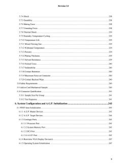
Revision 2.0 5.7.4 Shock 238 5.7.5 Durability..... 238 5.7.6 Mating Force 238 5.7.7 Unmating Force.......... 238 5.7.8 Thermal Shock. 239 5.7.9 Humidity Temperature Cycling 239 5.7.10 Temperature Life...... 239 5.7.11 Mixed Flowing Gas:... 239 5.7.12 Withstand Temperature 239 5.7.13 Porosity. 239 5.7.14 Plating Thickness. 239 5.7.15 Solvent Resistance..... 239 5.7.16 Normal Force.... 240 5.7.17 Solderability.. 240 5.7.18 Contact Retention. 240 5.7.19 Maximum Force on Connector. ””*.-r-r- 240 5.7.20 Contact Backout Wipe.... 240 5.8 Safety Requirements..... 240 5.9 Add-in Card Mechanical Sample. 240 5.10 Connector Qualification.... 241 5.10.1 Sample Size Per Group............ 241 5.10.2 Test Sequence. 241 6.System Configuration and A.G.P.Initialization.. 243 6.1 POST-time Initialization.. 243 6.1.1 A.G.P.Master Devices..... 243 6.1.2 A.G.P.Target Devices.... .244 6.1.3 Corelogic Ports....... 245 6.1.3.1 Processor Port......... 245 6.1.3.2 System Memory Port. 245 6.1.3.3 PCI Port.… 245 6.1.3.4 A.G.P.Port...... 245 6.1.4 Boot-time VGA Display Device(s). 247 6.1.5 Operating System Initialization 247 9
Revision 2.0 9 5.7.4 Shock........................................................................................................................................................ 238 5.7.5 Durability.................................................................................................................................................. 238 5.7.6 Mating Force ............................................................................................................................................ 238 5.7.7 Unmating Force ........................................................................................................................................ 238 5.7.8 Thermal Shock.......................................................................................................................................... 239 5.7.9 Humidity Temperature Cycling ................................................................................................................ 239 5.7.10 Temperature Life .................................................................................................................................... 239 5.7.11 Mixed Flowing Gas: ............................................................................................................................... 239 5.7.12 Withstand Temperature .......................................................................................................................... 239 5.7.13 Porosity................................................................................................................................................... 239 5.7.14 Plating Thickness.................................................................................................................................... 239 5.7.15 Solvent Resistance.................................................................................................................................. 239 5.7.16 Normal Force.......................................................................................................................................... 240 5.7.17 Solderability ........................................................................................................................................... 240 5.7.18 Contact Retention ................................................................................................................................... 240 5.7.19 Maximum Force on Connector ............................................................................................................... 240 5.7.20 Contact Backout Wipe............................................................................................................................ 240 5.8 Safety Requirements........................................................................................................................................ 240 5.9 Add-in Card Mechanical Sample..................................................................................................................... 240 5.10 Connector Qualification ................................................................................................................................ 241 5.10.1 Sample Size Per Group........................................................................................................................... 241 5.10.2 Test Sequence......................................................................................................................................... 241 6. System Configuration and A.G.P. Initialization .................................................................243 6.1 POST-time Initialization.................................................................................................................................. 243 6.1.1 A.G.P. Master Devices ............................................................................................................................. 243 6.1.2 A.G.P. Target Devices.............................................................................................................................. 244 6.1.3 Corelogic Ports ......................................................................................................................................... 245 6.1.3.1 Processor Port.................................................................................................................................... 245 6.1.3.2 System Memory Port ......................................................................................................................... 245 6.1.3.3 PCI Port ............................................................................................................................................. 245 6.1.3.4 A.G.P. Port ........................................................................................................................................ 245 6.1.4 Boot-time VGA Display Device(s)........................................................................................................... 247 6.1.5 Operating System Initialization ................................................................................................................ 247

Revision 2.0 6.1.6 PCI Status Register .248 6.1.7 Capabilities Pointer-(Offset 34h)........... .248 6.1.8 Capability Identifier Register (Offset=CAP_PTR) 248 6.1.9 Status Register (Offset CAP PTR+4).................. 249 6.1.10 Command Register -(Offset CAP_PTR+8) 250 6.2 A.G.P.Master MDA Resource Use Restrictions. 251 6.3 Multifunction A.G.P.Master......... 252 6.3.1 A.G.P.Configuration Registers... 254 6.3.2 Internal Arbiter............ 255 6.3.3 Deadlock Avoidance................ 255 10
Revision 2.0 10 6.1.6 PCI Status Register................................................................................................................................... 248 6.1.7 Capabilities Pointer - (Offset 34h)............................................................................................................ 248 6.1.8 Capability Identifier Register (Offset = CAP_PTR)................................................................................ 248 6.1.9 Status Register (Offset CAP_PTR + 4) .................................................................................................... 249 6.1.10 Command Register - (Offset CAP_PTR + 8) ........................................................................................ 250 6.2 A.G.P. Master MDA Resource Use Restrictions ............................................................................................. 251 6.3 Multifunction A.G.P. Master ........................................................................................................................... 252 6.3.1 A.G.P. Configuration Registers ................................................................................................................ 254 6.3.2 Internal Arbiter ......................................................................................................................................... 255 6.3.3 Deadlock Avoidance ................................................................................................................................ 255
按次数下载不扣除下载券;
注册用户24小时内重复下载只扣除一次;
顺序:VIP每日次数-->可用次数-->下载券;
- 《计算机维护维修 Computer Load & Repair》课程教学资源(文献资料)计算机天空电脑芯片级主板培训教材.pdf
- 《计算机维护维修 Computer Load & Repair》课程教学资源(文献资料)Information Technology - AT Attachment with Packet Interface – 7 Volume 3(ATA/ATAPI-7 V3).pdf
- 《计算机维护维修 Computer Load & Repair》课程教学资源(文献资料)Thermally Advantaged Chassis(TAC)Design Guide.pdf
- 《计算机维护维修 Computer Load & Repair》课程教学资源(文献资料)JEDEC DESIGN STANDARD DESIGN REQUIREMENTS FOR OUTLINES OF SOLID STATE AND RELATED PRODUCTS.pdf
- 中国地质大学(武汉):《汇编语言程序设计 Assembly Program Design》课程教学资源(课件讲稿)第六章 汇编语言高级编程.pdf
- 中国地质大学(武汉):《汇编语言程序设计 Assembly Program Design》课程教学资源(课件讲稿)第八章 中断及中断系统.pdf
- 中国地质大学(武汉):《汇编语言程序设计 Assembly Program Design》课程教学资源(课件讲稿)第七章 I/O程序设计.pdf
- 中国地质大学(武汉):《汇编语言程序设计 Assembly Program Design》课程教学资源(课件讲稿)第四章 汇编语言程序.pdf
- 中国地质大学(武汉):《汇编语言程序设计 Assembly Program Design》课程教学资源(课件讲稿)第五章 汇编程序设计.pdf
- 中国地质大学(武汉):《汇编语言程序设计 Assembly Program Design》课程教学资源(课件讲稿)第二章 8086微处理器.pdf
- 中国地质大学(武汉):《汇编语言程序设计 Assembly Program Design》课程教学资源(课件讲稿)第三章 寻址方式.pdf
- 中国地质大学(武汉):《汇编语言程序设计 Assembly Program Design》课程教学资源(课件讲稿)第一章 汇编语言基础.pdf
- 中国地质大学(武汉):《汇编语言程序设计 Assembly Program Design》课程教学资源(实验课件)综合实验(共十个).pdf
- 中国地质大学(武汉):《汇编语言程序设计 Assembly Program Design》课程教学资源(实验课件)创新实验(共三个).pdf
- 中国地质大学(武汉):《汇编语言程序设计 Assembly Program Design》课程教学资源(实验课件)基础实验(共五个).pdf
- 中国地质大学(武汉):《汇编语言程序设计 Assembly Program Design》课程教学资源(试卷习题)第1-4章习题.pdf
- 中国地质大学(武汉):《汇编语言程序设计 Assembly Program Design》课程教学资源(试卷习题)自测试题2(含答案).pdf
- 中国地质大学(武汉):《汇编语言程序设计 Assembly Program Design》课程教学资源(试卷习题)自测试题1(含答案).pdf
- 中国地质大学(武汉):《多媒体技术应用 Multimedia Technology》课程教学资源(课件讲稿)第六章 动画制作.pdf
- 中国地质大学(武汉):《多媒体技术应用 Multimedia Technology》课程教学资源(课件讲稿)第五章 视频信息处理.pdf
- 《计算机维护维修 Computer Load & Repair》课程教学资源(文献资料)计算机维修技术(第2版)Windows 2000/XP 服务说明.pdf
- 《计算机维护维修 Computer Load & Repair》课程教学资源(文献资料)计算机维修技术(第2版)Windows XP 注册表常用项值.pdf
- 《计算机维护维修 Computer Load & Repair》课程教学资源(文献资料)计算机维修技术(第2版)Windows 2000/XP 常见系统进程.pdf
- 《计算机维护维修 Computer Load & Repair》课程教学资源(文献资料)主板维修流程图.pdf
- 《计算机维护维修 Computer Load & Repair》课程教学资源(文献资料)计算机维修技术(第2版)Windows 下病毒和不良进程.pdf
- 《计算机维护维修 Computer Load & Repair》课程教学资源(文献资料)开机显示内容及相关故障判断.pdf
- 《计算机维护维修 Computer Load & Repair》课程教学资源(文献资料)主板维修思路.pdf
- 《计算机维护维修 Computer Load & Repair》课程教学资源(文献资料)維修簡單判斷流程圖.pdf
- 《计算机维护维修 Computer Load & Repair》课程教学资源(文献资料)计算机维修技术(第2版)POST卡故障代码含义速查表.pdf
- 《计算机维护维修 Computer Load & Repair》课程教学资源(文献资料)“El Torito” Bootable CD-ROM Format Specification Version 1.0.pdf
- 《计算机维护维修 Computer Load & Repair》课程教学资源(文献资料)USB 技术(Usb2.0的协议规范、USB的电气特性、协议层、USB设备架构、USB主机硬件与软件、集线器规范).pdf
- 《计算机维护维修 Computer Load & Repair》课程教学资源(文献资料)1394 Open Host Controller Interface Specification Release 1.1.pdf
- 《计算机维护维修 Computer Load & Repair》课程教学资源(文献资料)计算机维修技术(第2版)CPU插座类型与适用产品系列.pdf
- 《计算机维护维修 Computer Load & Repair》课程教学资源(文献资料)计算机维修技术(第2版)64位DDR2 SDRAM Unb-DIMM内存条引脚功能定义(240脚).pdf
- 《计算机维护维修 Computer Load & Repair》课程教学资源(文献资料)计算机维修技术(第2版)VGA接口定义.pdf
- 《计算机维护维修 Computer Load & Repair》课程教学资源(文献资料)计算机维修技术(第2版)64位DDR3 SDRAM Unb-DIMM内存条引脚功能定义(240脚).pdf
- 《计算机维护维修 Computer Load & Repair》课程教学资源(文献资料)计算机维修技术(第2版)常见BIOS参数设置说明.pdf
- 《计算机维护维修 Computer Load & Repair》课程教学资源(文献资料)计算机维修技术(第2版)DDR3笔记本内存引脚信号.pdf
- 《计算机维护维修 Computer Load & Repair》课程教学资源(文献资料)计算机维修技术(第2版)各种显示模式屏幕大小.pdf
- 《计算机维护维修 Computer Load & Repair》课程教学资源(文献资料)计算机维修技术(第2版)BIOS报警信号一览表.pdf
